Page
FCC Information U.S.A
Important Notice for the United Kingdom
Important Safety Instructions
Precautions
Connections
Label shown below is located on the rear of this product
Laser properties of the Drive
Internal Hard Disk Precautions
Contents
AUX
Midi
Remember to back up your data
Before you start
Introduction
Using the CD-RW drive
About the built-inCD-RW drive Using the CD-RW drive
About the built-in CD-RW drive
Handling
Installing an optional card
Installing an optional card
Installing an optional card
Available optional cards
Before you start
Features of the AW2400
Plenty of input channels with professional features
Introducing the AW2400
Mixer section
Recorder section
Connecting to a Computer
AW2400 terminology
Recorder section
CD-RW drive
Mixer section
Locate points/markers
Channels
Mixing Layers
Overall
Parts of the AW2400 and what they do
Parts of the AW2400 and what they do
Top panel
Quick Navigate section
Analog Input section
Work Navigate section
Display section
SEL keys Stereo SEL key
On keys Stereo on key
Faders
Stereo fader
Scene/Automix/USB section
Selected Channel section
Monitor section
Data entry/control section
Locate/Number section
Layer section
Remote key
Locate section
Transport section
Rear panel
Front panel
Slot
Basic operation of the AW2400
Accessing a screen/page
Switching a button on/off
Press the key or knob for the desired screen
F1-F4 keys correspond to the tabs as follows
Using the Locate Keys To Enter Characters & Numbers
Entering text
Switching Mixing Layers
Using the Selected Channel section
Selected Key Lit Knob
DYN
Dynamics Screen
Introducing the AW2400
Connection and Setup
Connection
Turning the power on/off
Turning the power on
Turning the power off shut down
Turning the power on/off
Adjusting the input level
Adjusting the input level
MIC/LINE Input XLR jacks
MIC/LINE Input TRS phone jacks
Input channel input levels are displayed at the top
Listening to the demo song
Loading the demo song
Press the Work Navigate section Song key
Song list
Playing the demo song
Demo song will begin playing
To stop the song, press the Stop key
Playing the demo song
Signal flow when using a sound clip
Recording to a sound clip
Recording a sound clip
Mixer section
Tempo
Time signature
Metronome button
Metronome knob
Playing a sound clip
Press the Play key to hear the recorded sound clip
Specifying the End point
Playing a sound clip
Recording to a sound clip
Move the cursor to the NEW button and press the Enter key
Track recording
Creating a new song
Cursor to the OK button, and press
Select the buttons of the items you want to
Carry over from the current song, move
Direct recording and Mixed recording
Direct recording
Direct recording and Mixed recording
MIC/LINE Input jacks Stereo Output
Bus
Mixed recording
Channel
Assigning input signals to tracks Direct recording
Display will appear as shown here
Raise the Stereo fader to the 0 dB posi- tion
To Adjust Volume/Balance
To Adjust Pan
Monitor signal flow during recording
This completes the patch setup for direct recording
Assigning input signals to tracks Mixed recording
Press the SEL keys for the record-desti- nation tracks
Set the input channel 1-8 faders as required
Direct recording and Mixed recording Recording on a track
Recording on a track
To stop recording, press the Stop key
Saving the current song
If you want to redo the recording, press the UNDO/REDO key
Move the cursor to the Save button and press the Enter key
Recording on a track Saving the current song
Pairing channels
Pairing
Monitor screen used for channel pairing
Popup window will appear, asking you to confirm
Popup window contains the same items as
Applying EQ To an Input Signal
EQ settings are available via this
Applying EQ To an Input Signal
Repeat steps 5 and 6 to set all bands as required
Applying Compression to an Input Signal
Compressor settings are available via this
Applying Compression to an Input Signal
Dynamics screen will appear
Using the Metronome
Activating the metronome and setting the tempo and vol- ume
Handy Recording Functions
Popup window confirming the recall operation will appear
Switching virtual tracks
Tempo map events
Tempo can be set from 30 to 250 BPM
Time signature can be set from 1/4 to 8/4
Using the Undo List
Press and hold the UNDO/REDO key
Undo List popup window will appear
Undo list
Signal flow when overdubbing
Overdubbing
About overdubbing
Input jacks Track
Assigning the input signal to a track
Assigning the input signal to a track
Setting the mix balance and pan
Setting the mix balance and pan
Adjust the pan in the same way for the other track channels
Overdubbing
Overdubbing
Recording will begin
Punch-in/out
Punch-in/out
Manual punch-in/out
To rehearse the auto punch-in/out, press the Play key
Following diagram shows the auto punch-in/out procedure
Overdubbing
Signal flow during mixdown
About mixdown and bouncing
About mixdown and bouncing
Signal flow during bouncing
Bouncing differs from mixdown in the following ways
Mixdown procedure
Digital
Mastering Library popup window will appear
Hint
Meter screen Master page will appear
Save the song
Playing back the stereo track
Switch the ST TR Mode ON/OFF button on
Playing back the stereo track
Bounce ping-pong recording procedure
Play Track
Return
Record Track
Bus 1 and Bus 2 output levels
Bounce ping-pong recording procedure
Convenient functions for mixdown/bounce
Fader Group assignments
Mute Group assignments
Repeat steps 2-3 to make assignments for other mute groups
Buttons E-H can be turned on/off independently
Operate a channel that is assigned to a mute group
Using the Solo function
To defeat the Solo function, press the Solo key once again
Mixdown and bounce operations
Transport/Locate Operation
Transport Section Keys
Move To a Specified Location
Enter the locate point in measures/beats
Using the locator
Displayed Character Locate Type Number
Using the locator
Locate points correspond to the following keys
Using markers
Using markers
You can assign markers while the song is playing or stopped
Press the Mark key
Adjusting the position of a locate point or marker
Markers
Adjusting the position of a marker
List
Erasing a marker
Erasing a locate point or marker
Erasing a locate point
Current location Song track Nudge time
Finding a location while viewing the waveform
Track
Scale
AMP
Finding a location while viewing the waveform
Meters
Level Meter Types
Level Meter Types
Meter screen Output page F4 key
Peak Hold button
Patching and signal flow
Input signal patching
Patching for Direct Recording
Or by pressing the F1 key after pressing 11 the Record key
Input signal patching
Remain
Direct OUT
Multi Connection ON/OFF button
Indication in the screen will be as follows
101
Patching for Mixed Recording
This area indicates the connection status of tracks 1
This indicates the remaining recordable time
102
103
Proceed with recording
For details on recording, refer to Track recording → p
Output signal patching
Omni OUT Assign field
Option I/O Slot OUT Assign field
ST OUT Assign field
Channel Operation
Input channels
Track channels Effect return channels
105
Channel Pair Indicator
Phase button, Gate button
Initialize button
ATT button, EQ button
Comp
Insert EFF
BUS1, BUS2, ST
REC TR
Channel Library Operation
Calling the Channel Library screen
EQ/COMP
Source Channel
109
Storing Channel Library settings
Move the cursor to the Store button and press the Enter key
Popup window confirming the clear operation will appear
Erasing Channel Library settings
Move the cursor to the Clear button and press the Enter key
AUX Send Level Adjustment
Adjusting AUX send levels via AUX screen
About the AUX buses
111
Adjusting AUX send levels via Selected Channel section
112
Using external effects with the AUX buses
This assigns the AUX1 bus signal to Omni OUT jack
AUX1 screen will appear
Press the Display section F2 key to dis- play the Track
Signal Flow When Using an External Effect Processor
EQ key so that its indicator lights, then
Press the Selected Channel section PAN
Fully left and right, respectively
Effects
About the Internal Effects
Effect Sends and Returns
Channel Insertion
Recalling Effect Library settings
Library setting will be recalled
Effect screen will appear
Press the Display section F4 key to call the FX Lib.
Applying Effects via Send and Return
Effect screen FX Input Input field
Effect screen FX Track Track field
117
118
Select PRE for pre-fader or Post for post-fader send
Effect screen FX Edit page will appear
Signal flow for the selected channel will be dis- played
Inserting an Effect Into a Channel
Popup window includes the following items
119
Signal flow is as follows
Internal effect inserted pre-EQ input channel
External effect inserted pre-EQ Input channel
120
Editing Effects
Name
Type
Used AS
Effect Library Operations
Call the Effect Library Screen
Changing Effect Library Names
122
Storing Effect Library settings
Erasing Effect Library settings
To actually erase the selected setting move
Cursor to the OK button and press Enter key 123
Correcting a Vocal Track Pitch Fix
Correcting a Vocal Track Pitch Fix
124
This will select the Pitch FIX display
Pitch FIX field
Control field
Parameters field
Master Tuning field
FIX Note field
Move the cursor to the Exit button and press Enter
126
127
Track operations and editing
About the AW2400’s tracks
Viewing all audio tracks
Audio track operations
About audio tracks
Switching the virtual track of an audio track
Muting a specific audio track
Virtual track name
Indicates the track number
Stereo track operations
Editing virtual track names for an audio track
About the stereo track
Edited name will be applied
131
Recording on the stereo track
Playing back the stereo track
132
Switching the virtual track of the stereo track
Editing the name of a virtual track for the stereo track
Trigger Track Function
About Trigger Track
133
Trigger Track Function
Normal button
Trigger button
Group
Fader Start button
Editing tracks
136
Basic procedure for track editing
Select the editing command
Execute the command
Select the tracks to edit
Specify the editing region
Select the virtual track that you want to edit
List of editing command
Parameters are the same as for the Erase command
List of editing command
Parameter list
From Track
139
Start End From Track To Start
List of editing command When measure lock = on
140
Measure Lock Start End From Track To Start
From Track To Start
Time Compression/Expansion
If you set Ratio = 50%
If you set Ratio = 200%
141
Pitch Pitch Change
142
Press the Enter key to confirm the edit command
Importing audio data/WAV files
Insert a CD into the CD-RW drive
You can import data from the following types of media
144
File
Total
145
Importing audio data from another song
Sort
To TR/To V.TR
146
147
Pan Control
Pan Control via the PAN/EQ Screen
148
Adjusting pan via Selected Channel section knob
Pan Control via Selected Channel section
149
Band EQ
EQ Control via the PAN/EQ Screen
EQ Control via the Selected Channel section
Using the Gates
Dynamics Processing
Parameter
151
Using the Compressors
Compressor Control via Dynamics screen
Compt ON/OFF button
Position field
Compressor Control via Selected Channel section
153
Selected Channel Knobs Parameters
Threshold Ratio Gain
Recalling EQ Library settings
Recalling Gate Library settings
EQ/Dynamics Processor Library Operation
154
155
Recalling EQ/Dynamics Library settings
Access the page containing the library to be edited
Changing EQ/Dynamics Library Names
156
Storing EQ/Dynamics Library settings
Erasing EQ/Dynamics Library settings
Cursor to the OK button and press
157
158
Scene Memory
About Scene Memory
Scene Memory Operation
Protect button
Renaming a scene
Recalling scene data
To the OK button and press the Enter
Key. For details on entering a name
Storing scene data
Deleting scene data
Scene will be stored
Here’s how you can delete unwanted scene data
Using the Recall Safe function
162
Moving scenes
Source list
Destination list
163
164
Song management
About songs
Song Organization
Song Bit Depth
Song Folder Organization
166
About songs
AW2400-1 Drive AW2400-2 Drive
Managing Your Songs
167
Creating a new song
Changes the order of songs displayed in the Song List
Currently-selected song
168
169
Song screen Setting page will appear
Editing the song name
170
Loading and Sorting Songs
Saving the current song
Deleting a song
Copying a song
Move the cursor to the Copy button and press the Enter key
171
Song Protection
Optimizing a song
Popup window will ask you to confirm the optimize operation
172
Importing data from an existing song
173
Editing various settings for the song
Editing various settings for the song
174
ABS absolute time
Creating a tempo map
Editing a tempo map event
Step
Measure
Event Range Content
Adding a tempo map event
Deleting a tempo map event
Selected event will be deleted
Backing up songs
177
Backing up songs Restoring songs
Restoring songs
178
Restore button
System button
179
Restoring songs
Mark will appear for songs selected to be restored
Compatible with the other AW-series
Information will be read from the inserted CD-R/RW media
180
ENABLE/DISABLE button
Automix
About Automix
Automix Operation
Command field
Creating a New Automix Recording
Overwrite field
Free
Move the cursor to the Mode field and press the REC button
Recording the Automix Data
Press the top-panel Play key to start song playback
183
CH ON/FADER
AUX/EFFECT Send on
AUX/EFFECT Send
PAN
Automix Playback
Punch In and Out of Automix
To stop Automix playback press the top- panel Stop key
Return Time Operation
Command Editing Automix data In a Specified Region
Move the cursor to the Mode field and turn the REC button on
Recorded Automix data will be updated
Operate the fader as required
Command
When the Erase command is selected
When the Copy or Move command is selected
Channel/Region
188
Editing Individual Automix Events
Param
Time
189
Automix Library Operation
About the Automix Library
Changing Automix Names
Protect
Storing Automix settings
Recalling Automix settings
Erasing Automix settings
191
Protecting Automix Data
192
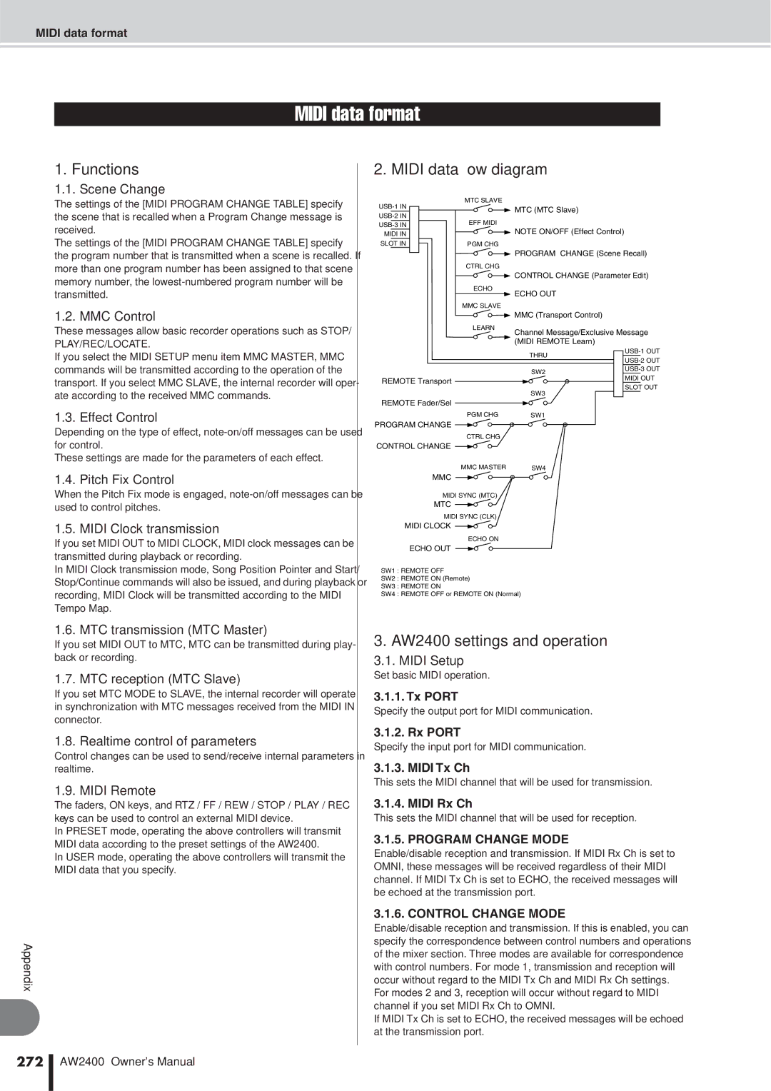
What you can do using Midi
193
Basic Midi Settings
Port field
Program Change field
Control Change field
195
Control Change Mode box
When Control Change Mode =
196
CC# Parameter
197
Midi Synchronization Message Setup
198
Offset
199
Connecting to External Equipment
Connecting to External Equipment
This sets the AW2400 to function as MTC master
Turn on the Slave button in the MMC field
Assign scenes to program changes
Play back the external Midi device
Program change number
Scene
Changes
Midi Clock Control Changes
With a built-in sequencer
Computer-based Sequencer application
203
Select a Control Change Mode
Play back the AW2400 song from the begin- ning
Using the Midi Remote function
Using the Midi Remote function presets
About the Midi Remote function
Messages that can
Mode box
Volume/Rec TR
Volume
Cubase Logic Sonar Protools
206
Using User-defined Remote function
USER1 USER2 USER3 USER4
This enables the Remote function
Remotely controlling Tone generator module
Learn button
Midi message
Operate the AW2400 faders and on keys
208
Using the test tone oscillator
Utility functions
Waveform
209
Nudge Play Mode
AW2400 Preferences
Nudge Time
Preroll Time
211
Postroll Time
Direct OUT Extract Position
Initializing the internal hard disk
Cluster field
Set the disk cluster size to either 32K or 64K
212
Creating an audio CD
Creating an audio CD
CD-R
CD-RW
Writing an audio CD
Track At Once
Disc At Once
214
Basic settings for the CD-RW drive
Writing audio data
If you turn on Track AT Once button
If you turn on the Disc AT Once button
216
Writing Track At Once
Inserted CD-RW will be automatically checked
Move the cursor to the ADD button and press the Enter key
217
Writing Disc At Once
Move the cursor to the Write button and press the Enter key
To finalize the disc, move the cursor to
OK button and press the Enter key
219
Finalizing CD-R/RW media
Popup window will ask you to confirm the finalize operation
220
Finalizing CD-R/RW media
Erasing CD-RW media
Buttons select the following erasure methods
221
Erasing CD-RW media
CD Play Mode button
Switches the CD Play function on/off
Playing an audio CD
Input CH MUTE/MIX button
223
Wordclock and Cascade Settings
Select the Wordclock Source
INT button
ST in button
2-15/16 buttons
IN, OUT
Using an HDR or DAW As Wordclock Master
Using an MD or DAT Recorder as Wordclock Master
Select a wordclock source via the Wordclock Source field
AW2400 As Wordclock Master
Cascade-connecting External Devices
226
Check the Status Of the Digital Input Signal
227
Plug-in Card Settings
Digital Stereo in connector status
Digital I/O card status
228
Midi Message Transfer Normal Mode
WAV File Transfer USB Storage Mode
USB Storage mode
What You Can Do With USB
230
WAV File Transfer USB Storage Mode
Mode
Turn on the AW2400
Two windows will appear
Case of Mac OS
231
Exiting the USB Storage Mode
Case of Mac OSX
Copying Exported WAV Files To the Computer
From TR
From V.TR
File Name
For details on how to enter a name, refer to
Importing Copied WAV Files From the Computer
Transport folder is located in the AW2400-2 drive
234
This field is for display only, and cannot be changed
235
236
Name Description
Appendix
237
238
EQ Parameter list
Title Parameter
Parameter # Title
239
LOW MID
240
Dynamics Parameters
Compressor CMP parameters
Parameter Value
CompanderH CPH CompanderS CPS parameters
241
Expander EXP parameters
242
Gate GAT and Ducking DUK parameters
Title Type Parameter Value
243
Gate Parameter list Compressor Parameter list
244
Compressor Parameter list
Reverb HALL, Reverb ROOM, Reverb STAGE, Reverb Plate
Early REF
One input, two output early reflections
Gate REVERB, Reverse Gate
Mono Delay
Stereo Delay
MOD. Delay
Delay LCR
Echo
Chorus
Flange
247
Phaser
Symphonic
Auto PAN
248
Tremolo
HQ. Pitch
Dual Pitch
Rotary
Ring MOD
MOD. Filter
Distortion
AMP Simulate
DYNA. Phaser
DYNA. Filter
DYNA. Flange
251
REV+CHORUS
REV-CHORUS
REV+FLANGE
252
REV-FLANGE
One input, two output reverb and flanger effects in series
REV+SYMPHO
REV-SYMPHO
254
DELAY+ER
REV-PAN
DELAY-ER
DELAY+REV
DELAY-REV
255
DIST-DELAY
Multi Filter
Two input, two output 3-band multi-filter 24 dB/octave
256
257
Gate
Band Dyna
258
259
260
261
262
Display message list
Messages
263
Popup messages
264
265
Special Notices
Contents of the CD-ROM
Installing USB Midi driver
Start your computer, then log in as Adminis- trator
Restart the computer
Click Continue
Click the Close button
Installing a remote file
Move the cursor to the list and press
268
Windows
Commands
269
Installing the Sonar template file
270
271
Type Receive From Send To #ch’s
272
Program Change Mode
Control Change Mode
MTC Sync Mode
Remote Port
MTC Sync Average
MTC Sync Offset
Midi Time Code Quarter Frame F1
Song Position Pointer F2
Timing Clock F8
Continue FB
MMC Fast Forward
MMC Record Strobe
MMC Record Exit
MMC Locate Target
Midi Implementation Chart
276
277
278
Input/Output
Digital Mixing Functions
Dimensions
279
280
Index
281
Gate
282
Recall Confirmation
283
Block diagram
Input
285
286
North America