AT-S79 Management Software User’s Guide
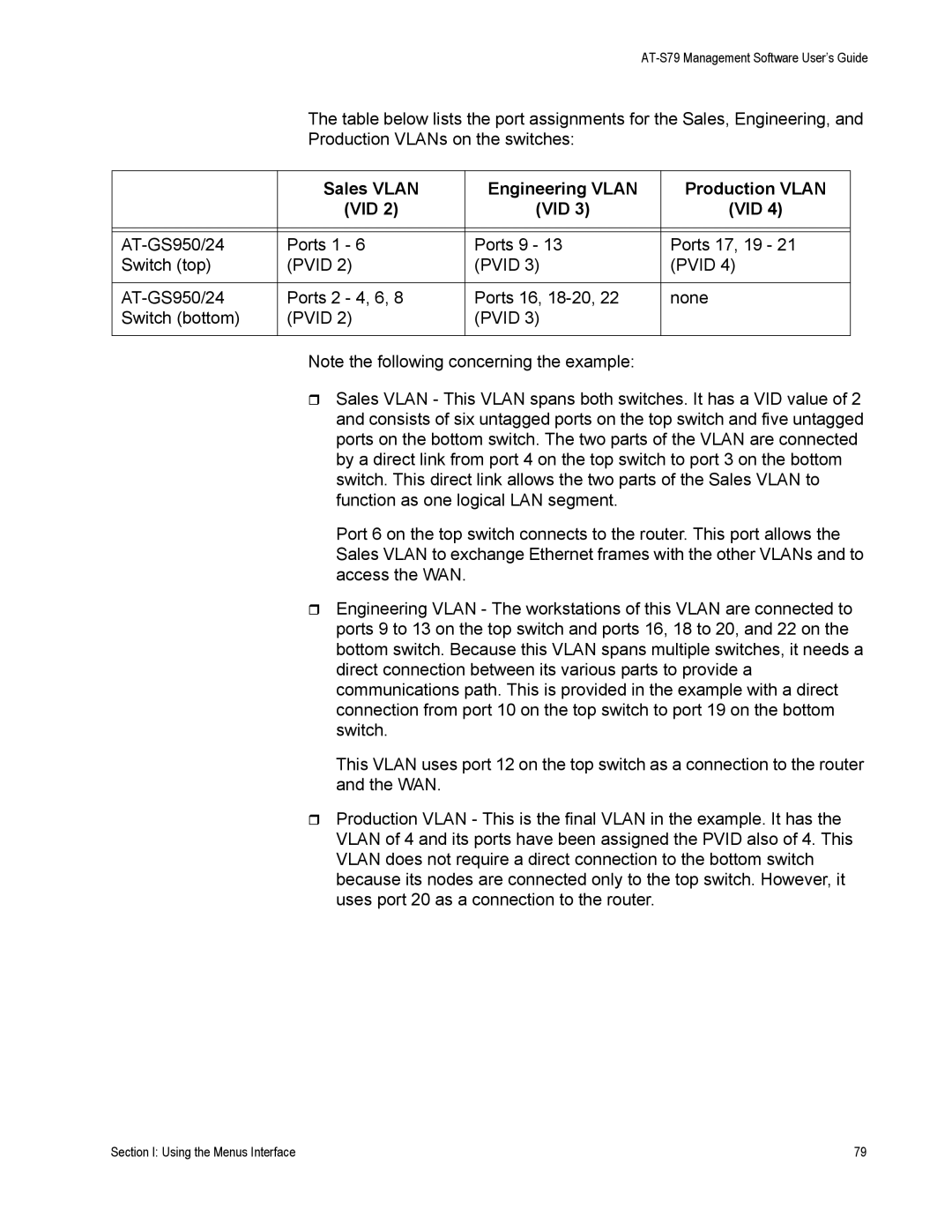
The table below lists the port assignments for the Sales, Engineering, and
Production VLANs on the switches:
| Sales VLAN | Engineering VLAN | Production VLAN |
| (VID 2) | (VID 3) | (VID 4) |
|
|
|
|
|
|
|
|
Ports 1 - 6 | Ports 9 - 13 | Ports 17, 19 - 21 | |
Switch (top) | (PVID 2) | (PVID 3) | (PVID 4) |
|
|
|
|
Ports 2 - 4, 6, 8 | Ports 16, | none | |
Switch (bottom) | (PVID 2) | (PVID 3) |
|
|
|
|
|
Note the following concerning the example:
Sales VLAN - This VLAN spans both switches. It has a VID value of 2 and consists of six untagged ports on the top switch and five untagged ports on the bottom switch. The two parts of the VLAN are connected by a direct link from port 4 on the top switch to port 3 on the bottom switch. This direct link allows the two parts of the Sales VLAN to function as one logical LAN segment.
Port 6 on the top switch connects to the router. This port allows the Sales VLAN to exchange Ethernet frames with the other VLANs and to access the WAN.
Engineering VLAN - The workstations of this VLAN are connected to ports 9 to 13 on the top switch and ports 16, 18 to 20, and 22 on the bottom switch. Because this VLAN spans multiple switches, it needs a direct connection between its various parts to provide a communications path. This is provided in the example with a direct connection from port 10 on the top switch to port 19 on the bottom switch.
This VLAN uses port 12 on the top switch as a connection to the router and the WAN.
Production VLAN - This is the final VLAN in the example. It has the VLAN of 4 and its ports have been assigned the PVID also of 4. This VLAN does not require a direct connection to the bottom switch because its nodes are connected only to the top switch. However, it uses port 20 as a connection to the router.
Section I: Using the Menus Interface | 79 |
