2. Hardware Orientation
Front Panel Sections
qçìÅÜ=pÅêÉÉå=jÉåì=pÉÅíáçå
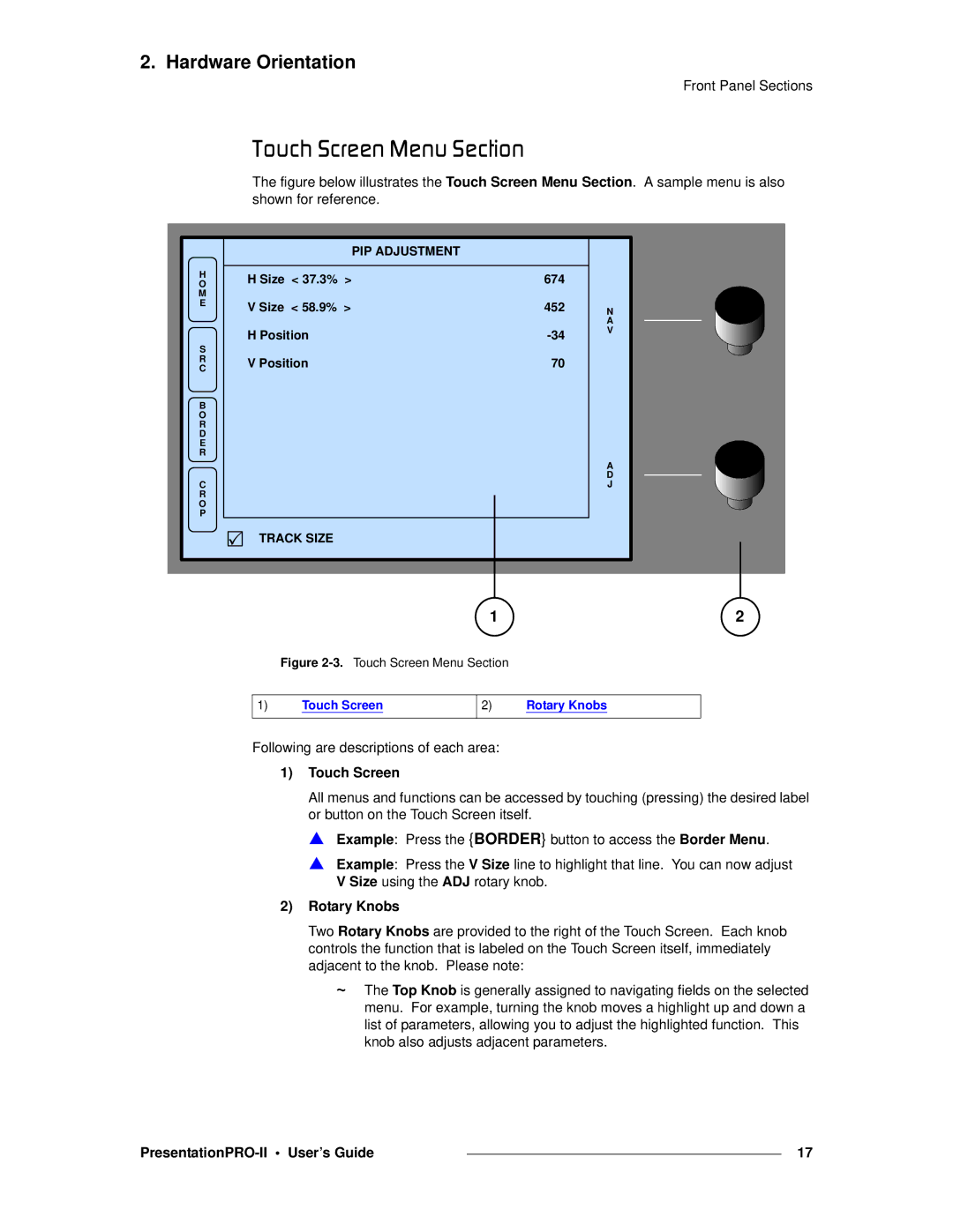
The figure below illustrates the Touch Screen Menu Section. A sample menu is also shown for reference.
|
| PIP ADJUSTMENT |
|
H | H Size < 37.3% > | 674 |
|
O |
| ||
M |
|
|
|
E | V Size < 58.9% > | 452 | N |
| |||
|
|
| A |
| H Position | V | |
S |
| ||
|
|
| |
R | V Position | 70 |
|
C |
| ||
B |
|
|
|
O |
|
|
|
R |
|
|
|
D |
|
|
|
E |
|
|
|
R |
|
|
|
|
|
| A |
C |
|
| D |
|
| J | |
R |
|
|
|
O |
|
|
|
P |
|
|
|
| 3 TRACK SIZE |
|
|
1 | 2 |
Figure 2-3. Touch Screen Menu Section
1)Touch Screen
2)Rotary Knobs
Following are descriptions of each area:
1)Touch Screen
All menus and functions can be accessed by touching (pressing) the desired label or button on the Touch Screen itself.
S Example: Press the {BORDER} button to access the Border Menu.
S Example: Press the V Size line to highlight that line. You can now adjust V Size using the ADJ rotary knob.
2)Rotary Knobs
Two Rotary Knobs are provided to the right of the Touch Screen. Each knob controls the function that is labeled on the Touch Screen itself, immediately adjacent to the knob. Please note:
~The Top Knob is generally assigned to navigating fields on the selected menu. For example, turning the knob moves a highlight up and down a list of parameters, allowing you to adjust the highlighted function. This knob also adjusts adjacent parameters.
|
| 17 |
|