2. Hardware Orientation
Front Panel Sections
~The Bottom knob is used to adjust the adjacent parameter, as labeled on the Touch Screen.
Important
There is no Enter button. If you adjust a value with the knobs, that function or value is immediately active.
pçìêÅÉ=pÉäÉÅíáçå=_ìë
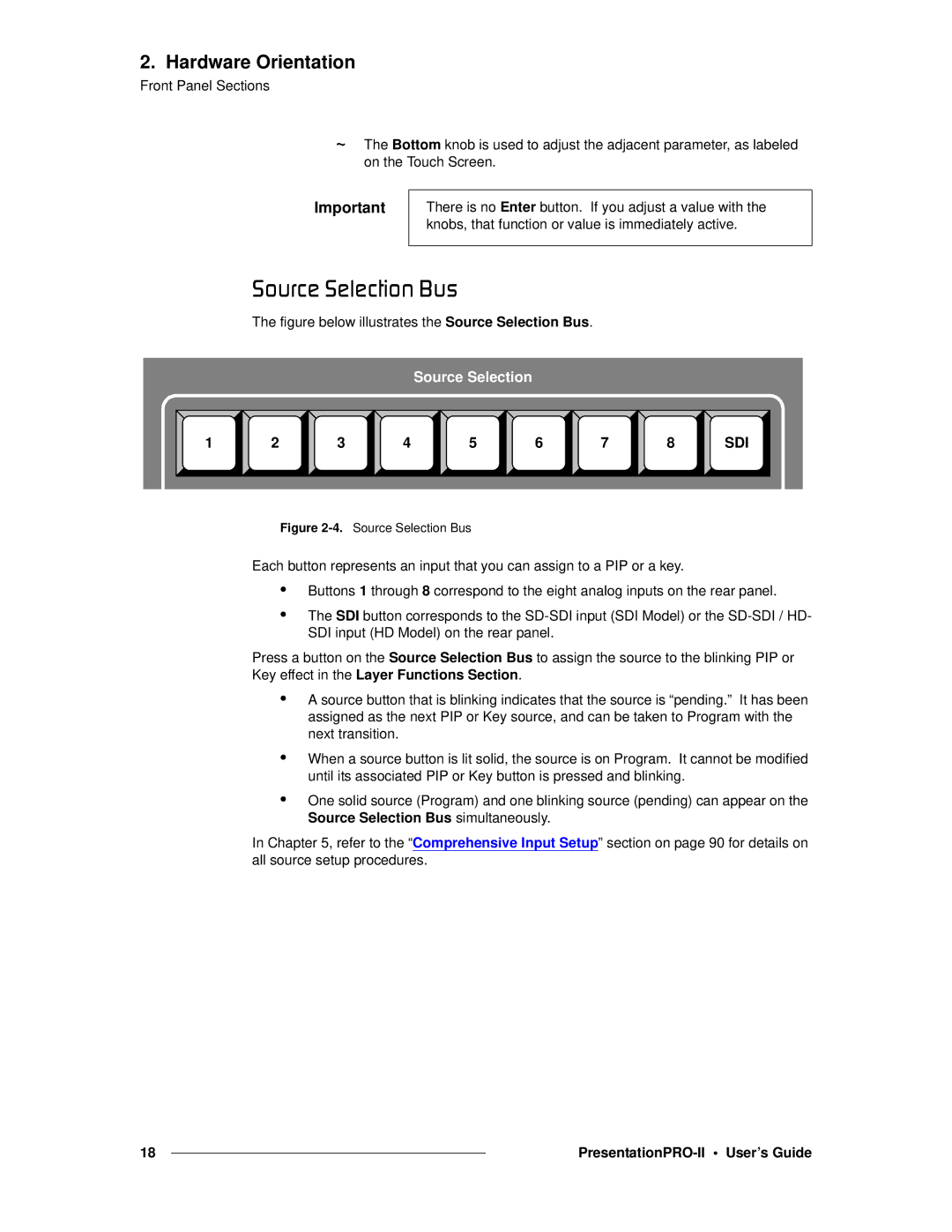
The figure below illustrates the Source Selection Bus.
Source Selection
1 | 2 | 3 | 4 | 5 | 6 | 7 | 8 | SDI |
Figure 2-4. Source Selection Bus
Each button represents an input that you can assign to a PIP or a key.
•Buttons 1 through 8 correspond to the eight analog inputs on the rear panel.
•The SDI button corresponds to the
Press a button on the Source Selection Bus to assign the source to the blinking PIP or Key effect in the Layer Functions Section.
•A source button that is blinking indicates that the source is “pending.” It has been assigned as the next PIP or Key source, and can be taken to Program with the next transition.
•When a source button is lit solid, the source is on Program. It cannot be modified until its associated PIP or Key button is pressed and blinking.
•One solid source (Program) and one blinking source (pending) can appear on the Source Selection Bus simultaneously.
In Chapter 5, refer to the “Comprehensive Input Setup” section on page 90 for details on all source setup procedures.
18 |
|
|
|
