3. Hardware Installation
Input Connection Chart
fåéìí=`çååÉÅíáçå=`Ü~êí=
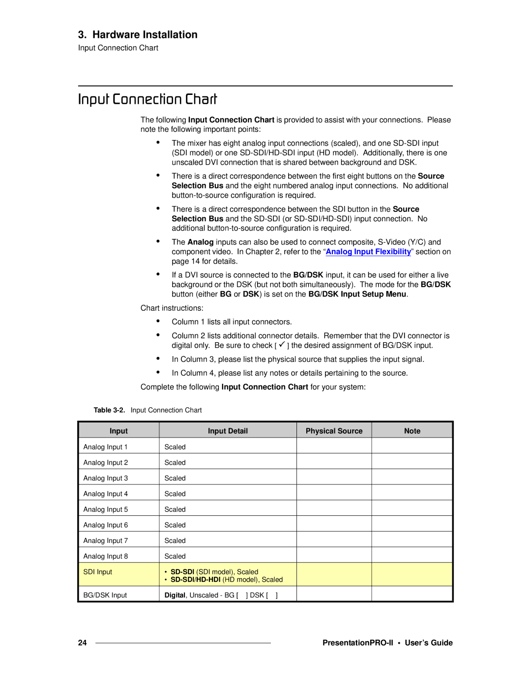
The following Input Connection Chart is provided to assist with your connections. Please note the following important points:
•The mixer has eight analog input connections (scaled), and one
•There is a direct correspondence between the first eight buttons on the Source Selection Bus and the eight numbered analog input connections. No additional
•There is a direct correspondence between the SDI button in the Source Selection Bus and the
•The Analog inputs can also be used to connect composite,
•If a DVI source is connected to the BG/DSK input, it can be used for either a live background or the DSK (but not both simultaneously). The mode for the BG/DSK button (either BG or DSK) is set on the BG/DSK Input Setup Menu.
Chart instructions:
•Column 1 lists all input connectors.
•Column 2 lists additional connector details. Remember that the DVI connector is digital only. Be sure to check [ 3 ] the desired assignment of BG/DSK input.
•In Column 3, please list the physical source that supplies the input signal.
•In Column 4, please list any notes or details pertaining to the source.
Complete the following Input Connection Chart for your system:
Table
Input |
| Input Detail |
| Physical Source | Note |
Analog Input 1 | Scaled |
|
|
| |
|
|
|
|
| |
Analog Input 2 | Scaled |
|
|
| |
|
|
|
|
| |
Analog Input 3 | Scaled |
|
|
| |
|
|
|
|
| |
Analog Input 4 | Scaled |
|
|
| |
|
|
|
|
| |
Analog Input 5 | Scaled |
|
|
| |
|
|
|
|
| |
Analog Input 6 | Scaled |
|
|
| |
|
|
|
|
| |
Analog Input 7 | Scaled |
|
|
| |
|
|
|
|
| |
Analog Input 8 | Scaled |
|
|
| |
|
|
|
|
|
|
SDI Input | • |
|
|
| |
| • |
|
| ||
BG/DSK Input | Digital, Unscaled - BG [ ] DSK [ | ] |
|
| |
24 |
|
|
|
