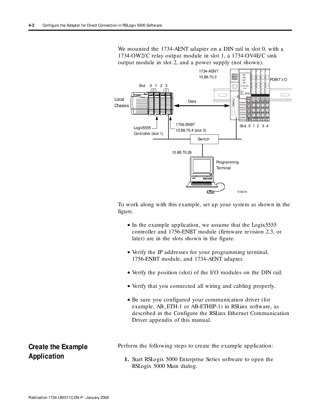
We mounted the
Slot 0 1 2 3
Local |
|
|
|
|
|
|
|
|
|
|
|
|
|
|
|
|
|
| Data |
|
| ||||
Chassis |
|
|
|
|
|
|
|
| ||||
|
|
|
|
|
|
|
|
|
|
|
| |
Logix5555 |
|
|
|
|
|
|
| |||||
|
|
|
|
|
|
| ||||||
|
|
|
|
|
|
|
| |||||
|
|
|
|
|
|
|
| |||||
|
|
|
|
|
|
|
| |||||
|
|
|
|
|
|
|
| |||||
|
|
|
|
|
|
|
| |||||
|
|
|
|
| 10.88.70.4 (slot 3) |
|
| |||||
|
|
|
|
|
|
|
| |||||
| Controller (slot 1) |
|
|
|
| |||||||
|
|
|
|
|
|
|
|
| ||||
|
|
|
|
|
|
|
| Switch |
|
|
| |
|
|
|
|
|
|
|
|
|
| |||
|
|
|
|
|
|
|
|
|
|
|
|
|
| POINT I/O |
Slot 0 1 2 | 3 4 |
Create the Example Application
10.88.70.26
Programming
Terminal
To work along with this example, set up your system as shown in the figure.
•In the example application, we assume that the Logix5555 controller and
•Verify the IP addresses for your programming terminal,
•Verify the position (slot) of the I/O modules on the DIN rail.
•Verify that you connected all wiring and cabling properly.
•Be sure you configured your communication driver (for example,
Perform the following steps to create the example application:
1.Start RSLogix 5000 Enterprise Series software to open the RSLogix 5000 Main dialog.
Publication