1734 POINT I/O Module/RSLogix 5000 Controller Tag Reference | |
|
|
1 Channel 15…24V dc Very
1 Channel 5V dc Very
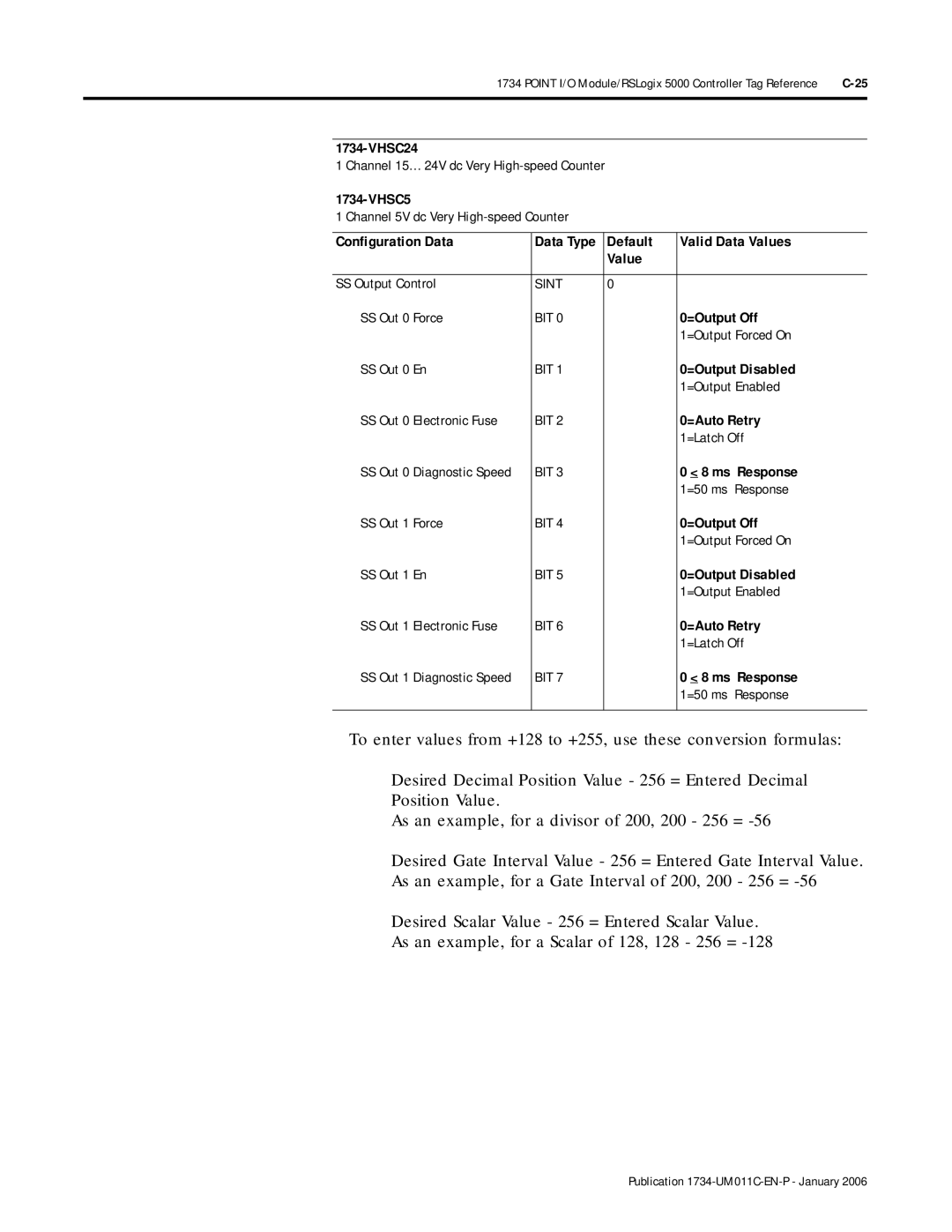
Configuration Data | Data Type | Default | Valid Data Values | |
|
|
| Value |
|
|
|
|
| |
SS Output Control | SINT | 0 |
| |
SS Out 0 Force | BIT 0 |
| 0=Output Off | |
|
|
|
| 1=Output Forced On |
SS Out 0 En | BIT 1 |
| 0=Output Disabled | |
|
|
|
| 1=Output Enabled |
SS Out 0 Electronic Fuse | BIT 2 |
| 0=Auto Retry | |
|
|
|
| 1=Latch Off |
SS Out 0 Diagnostic Speed | BIT 3 |
| 0 < 8 ms Response | |
|
|
|
| 1=50 ms Response |
SS Out 1 | Force | BIT 4 |
| 0=Output Off |
|
|
|
| 1=Output Forced On |
SS Out 1 | En | BIT 5 |
| 0=Output Disabled |
|
|
|
| 1=Output Enabled |
SS Out 1 | Electronic Fuse | BIT 6 |
| 0=Auto Retry |
|
|
|
| 1=Latch Off |
SS Out 1 | Diagnostic Speed | BIT 7 |
| 0 < 8 ms Response |
|
|
|
| 1=50 ms Response |
|
|
|
|
|
To enter values from +128 to +255, use these conversion formulas:
Desired Decimal Position Value - 256 = Entered Decimal
Position Value.
As an example, for a divisor of 200, 200 - 256 =
Desired Gate Interval Value - 256 = Entered Gate Interval Value.
As an example, for a Gate Interval of 200, 200 - 256 =
Desired Scalar Value - 256 = Entered Scalar Value.
As an example, for a Scalar of 128, 128 - 256 =