March 83-00003261, Revision C
Copyright
Contents
Site Planning
LEDs When The Array Is First Powered On Front-Panel LEDs
Configuration Overview
Troubleshooting Your Array
Setting Up the Serial Port Connection
RJ-45 Connector DB9 COM Port
Configuring a Microsoft Windows Server
Index Index-1
Page
Figures
Figure B-1
SANnet II 200 FC Jbod Array Attached to a Single HBA Port
Figures
Page
Tables
Controller Module and Battery Module LEDs
Power Supply LEDs Battery Status Indicators
How This Book Is Organized
Preface
Related Documentation
Typographic Conventions
Placing a Support Call
Technical Support
Dot Hill Welcomes Your Comments
Product and Architecture Overview
1SANnet II 200 FC, SATA, and Sata SE Array Front View
Comparison of FC, SATA, and Sata SE Arrays
Fibre Channel and Sata Array Architectures
SANnet II 200 FC Array Features
SANnet II 200 Sata and Sata SE Array Features
10K RPM
SANnet II 200 FC, SATA, and Sata SE Array Configurations
SFP
RAID I/O Controller Modules
Field-Replaceable Units
Disk Drives
2 I/O Expansion Modules
SANnet II 200 FC Array Disk Drives
Battery Module
Fibre Channel Technology Overview
Power and Fan Modules
Interoperability
FC Topologies
Fibre Hubs and Switches
FC Protocols
Scalability
Data Availability
Fibre Channel Architecture
Redundant Configuration Considerations
Active-to-Active Redundant Controller
Additional Software Tools
Page
Customer Obligations
Site Planning
Safety Precautions
Electromagnetic Compatibility
Electrical and Power Specifications
1Environmental Specifications
Environmental Requirements
3Physical Specifications
Physical Specifications
Rack Placement
2Power Specifications
Console and Other Requirements
Tabletop Placement
Preinstallation Worksheets
4Site Preparation Worksheet
5Host and Fabric Switch Connectivity Summarized
Opening Your Package
Unpacking Your Array
Checking the Package Contents
Mounting Your Array in a Rack or Cabinet
Customer-Provided Cables
Page
Connecting Your Array
1Front Bezel and Front Bezel Locks of an Array
Connecting Your Array
SANnet II 200 FC Array Connections
RAID Array Connections
SANnet II 200 Sata Array Connections
Servers and consoles FC devices
SANnet II 200 Sata SE Array Connections
Connecting the Chassis to AC Power Outlets
Page
6Installing a Cord Lock
Connecting the Chassis to DC Power Outlets
2DC Cable Wiring for Cable
1DC Cable Wiring for Cable
Cabling to Expansion Units
RAID array Expansion unit Loop a top drive ports
Setting Loop IDs on Expansion Units
9Front Bezel and Front Bezel Locks of an Array
3ID Switch Settings for Expansion Units
Reviewing Channels, Ports, and SFPs
Powering Up and Checking LEDs
Drive Port Connectivity in a Dual-Controller Array
SANnet II 200 FC Array Drive Ports
6Number of Host Ports and Supported Host Port Speeds
Host Port Connectivity in a Dual-Controller Array
SANnet II 200 Sata and Sata SE Arrays
16Host Channels on a Dual-Controller Sata SE Array
Default SFP Placement
Host port FC0 Drive port FC2 Host port FC4
Host port FC0 Host port FC1 Host port FC4
21SANnet II 200 FC JBOD/Expansion Unit Default SFP Placement
Changing Your SFP Configuration
Establishing Communications With An Array
Configuring a Host COM Port to Connect to a RAID Array
Choose Set IP Address →Address
Manually Setting a Static IP Address
Setting Up Out-of-Band Management Over Ethernet
# telnet IP-address
Adding an Expansion Unit to an Existing RAID Array
Choose Support →Downloads Click Firmware Downloads
Connecting Ports to Hosts
Power-On Sequence
Powering Off the Array
Page
Summary of Array Configuration
Configuration Overview
Page
Point-to-Point Configuration Guidelines
Page
Sample SAN Point-to-Point Configuration
Page
Server Switch PID 40 PID 43 SID 45 SID 46 Map LG0 to PIDs 40
Server Switch PID SID Map LG0 to PIDs 40
LUN
2Connection for Four Servers in a DAS Configuration
Sample DAS Loop Configuration
Server
RCC
Channel Primary Secondary Number ID Number
Connecting Two Hosts to One Host Channel Sata Only
Larger Configurations
Configuration Overview
Page
Checking LEDs
LEDs When The Array Is First Powered On
1Front-Panel LED Status When Array Is First Powered On
1Front-Panel LEDs
Front-Panel LEDs
2Front-Panel LEDs
2lists the front-panel LEDs and describes LED activity
3Drive LED Status
Drive LED Status
Correcting SES or PLD Firmware Version Conflicts
1 I/O Controller Module LEDs
Back-Panel LEDs
Activity Cache Ethernet active Ethernet link Battery
4I/O Controller Module and Battery Module LEDs
6I/O Expansion Module for a SANnet II 200 FC Expansion Unit
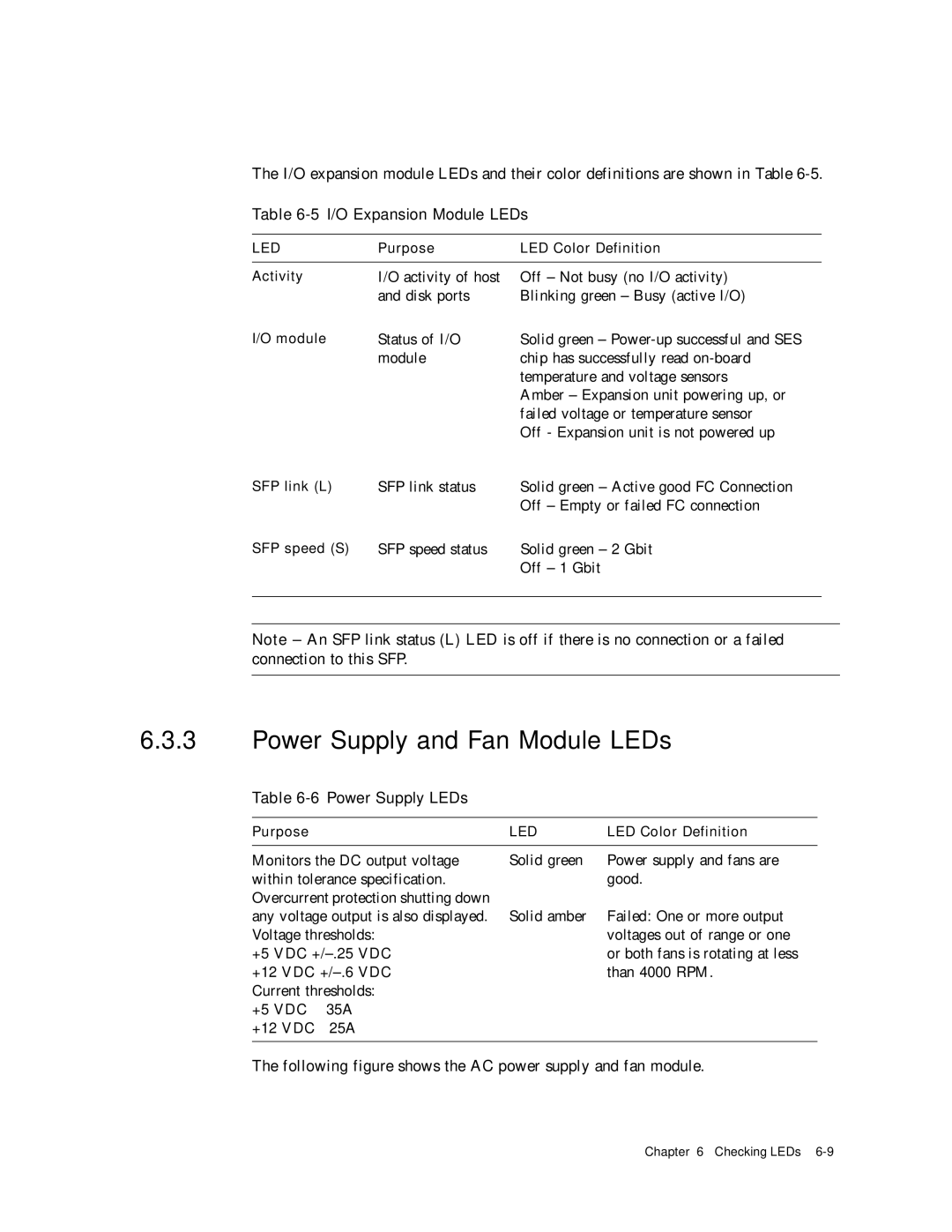
2 I/O Expansion Module LEDs
5I/O Expansion Module LEDs
Power Supply and Fan Module LEDs
6Power Supply LEDs
Following figure shows the DC power supply and fan module
Maintaining Your Array
Using Software to Monitor and Manage the Array
Other Supported Software
Out-of-Band Connections
In-Band Connections
Enabling Veritas DMP
1Battery Status Indicators
Battery Operation
Veritas Volume Manager ASL
Battery Status
Viewing Event Logs on the Screen
Page
Upgrading Firmware
Installing Firmware Upgrades
Controller Firmware Upgrade Features
Upgrading SES and PLD Firmware
Replacing the Front Bezel and Ear Caps
Placing the Bezel and Ear Caps Back Onto the Chassis
Removing the Front Bezel and Ear Caps
Page
Sensor Locations
Troubleshooting Your Array
1Cooling Element Sensors for FC, SATA, and Sata SE Arrays
Cooling Element Sensors
2Temperature Sensors for FC, SATA, and Sata SE Arrays
Temperature Sensors
4Voltage Sensors for Sata and Sata SE Arrays
Voltage Sensors
3Voltage Sensors for FC Arrays
5Power Supply Sensors for FC, SATA, and Sata SE Arrays
Silencing Audible Alarms
Power Supply Sensors
Page
Controller Failover
6Silencing Alarms
RAID LUNs Not Visible to the Host
Recovering From Fatal Drive Failure
Troubleshooting Your Array
Using the Reset Push Button
Power Supply and Fan Module
Troubleshooting Flowcharts
2Power Supply or Fan Module Flowchart, 1
Drive LEDs
3Power Supply or Fan Module Flowchart, 2
Page
4Drive LEDs Flowchart, 1
Front-Panel LEDs
5Drive LEDs Flowchart, 2
6Front-Panel LEDs Flowchart, 1
7Front-Panel LEDs Flowchart, 2
8Front-Panel LEDs Flowchart, 3
9Front-Panel LEDs Flowchart, 4
4 I/O Controller Module
10I/O Controller Module Flowchart
Page
SANnet II 200 FC, SATA, and Sata SE Array Specifications
SANnet II 200 FC, SATA, and Sata SE Array Highlights
Hardware Loop ID
Firmware Host-Side Connection Mode
Firmware Dynamic Load Balancing
Agency Approvals and Standards
Firmware LUN Filtering RAID-Based Mapping
Firmware Redundant Loops
ESD
Page
Supported Configurations Jbod Arrays
Using a Standalone Jbod Array SANnet II 200 FC Array Only
Known Limitations Affecting SANnet II 200 FC Jbod Arrays
Supported Operating Systems Jbod Arrays
Supported Host Platforms and Connection Methods Jbod Arrays
SANscape
SANscape CLI
Setting the Loop ID on a SANnet II 200 FC Jbod Array
SANscape Alert
Table B-2ID Switch Settings for SANnet II 200 FC Jbod Arrays
Changing Your ID Switch Setting
Single-Port Connection to a SANnet II 200 FC Jbod Array
Connecting SANnet II 200 FC Jbod Arrays
Dual-Port Connections to a SANnet II 200 FC Jbod Array
Jbod array
Changing Your SFP Configuration on Jbod Arrays
Choose View →Agent Options Management
Enabling SANnet II 200 FC Jbod Array Support
Jbod
Downloading Firmware to Disk Drives in a
Resizing LUNs Greater Than 1 Tbyte
Troubleshooting SANnet II 200 FC Jbod Arrays
Troubleshooting Hardware Issues
Troubleshooting Configuration Issues
Page
Jbod or expansion unit problem FC
Converting a Jbod to a RAID array
Table C-1Failed Component Alarm Codes
Failed Component Alarm Codes
Page
Cable Pinouts
RJ-45 Connector
Figure D-2RS-232 DB9 EIA/TIA 574 View of the Male End
DB9 COM Port
Setting Up the Serial Port Connection
Using the tip Command for Local Access to the Array
Determining the WWN in the Solaris Operating System
Page
Configuring a Microsoft Windows Server
Power up the array
Choose Start →Find →For Files or Folders
Choose Programs →Accessories →Command Prompt
Select Primary partition and click Next
Select Format this partition with the following settings
Appendix F Configuring a Microsoft Windows Server F-7
Determining the Worldwide Name for Microsoft Windows Servers
Configuring a Linux Server
Minicom -s
Accessing the Firmware Application From a Linux Server
Highlight Extended Firmware Settings and press Return
Checking the Adapter Bios
Making an ext3 File System for Linux
Multiple LUN Linux Configuration
Creating a File System
Mounting the File System Automatically
Creating a Mount Point and Mounting the File System Manually
Determining the Worldwide Name for Linux Hosts
Setting Up a Serial Port Connection
Configuring an IBM Server Running the AIX Operating System
Page
Kermitset line /dev/tty0p1
Using Smit to Enable an AIX Host to Recognize New LUNs
Creating a Volume Group
Creating a Logical Volume
Verifying That the New File System Is Mounted
Mounting the New File System
Figure H-2Network Address Corresponding to WWN
Determining the Worldwide Name for IBM Servers Running AIX
Configuring an HP Server Running the HP-UX Operating System
Page
# kermit
Attaching the Disk Array
Logical Volume Manager
Definitions of Common Terms
Creating a Physical Volume
# pvcreate /dev/rdsk/c12t6d2
# lvcreate -L 4092 /dev/vg02
Mounting the File System Manually
Creating an HP-UX File System
Determining the Worldwide Name for HP-UX Hosts
# fcmsutil/device-name
Index
Page
Index
Serial port parameters E-2,F-2,G-2,H-2,H-3,I-2, I
Index