As with many system administration tasks, you can use SAM to create and maintain logical volumes. However, some functions can only be performed with
I.5 Definitions of Common Terms
Volume groups are
Each volume group is divided into logical volumes, which are seen by the applications as individual disks. They can be accessed as either character or block devices and can contain their own file systems.
The underlying physical storage in a volume group consists of one or more physical volumes. A physical volume can be a single physical disk or a partition of a disk array.
Each physical volume is divided into units called physical extents. The default size of these units is 4 Mbyte, but can range in size from 1 Mbyte to 256 Mbyte. The maximum number of physical extents that a volume group can contain is 65,535. With the default size of 4 Mbyte, this limits the size of the volume group to 255 Gbyte.
To create a volume group larger than 255 Gbyte, you must increase the size of the physical extents when creating the volume group. Refer to vgcreate(1m) for further information.
I.6 Creating a Physical Volume
To use a storage resource in the LVM, it must first be initialized into a physical volume (also called an LVM disk).
1.Log in as root, or become superuser if you are not logged in with root user privileges.
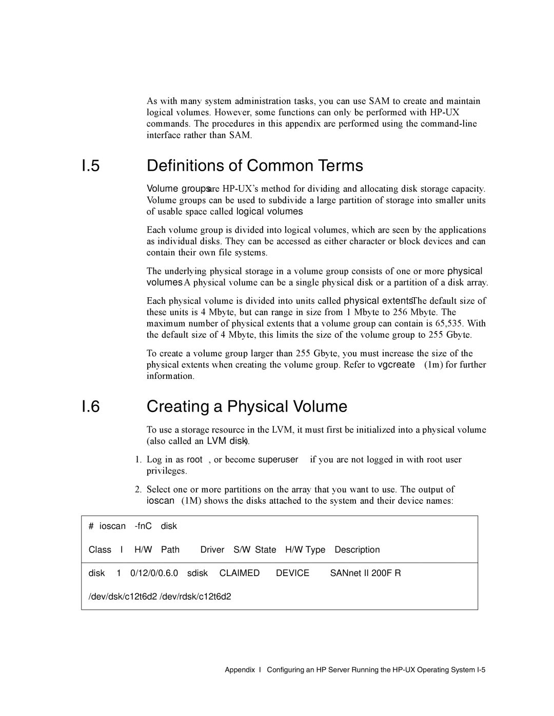
2.Select one or more partitions on the array that you want to use. The output of ioscan(1M) shows the disks attached to the system and their device names:
# ioscan |
|
|
|
| ||
Class | I | H/W Path | Driver | S/W State | H/W Type | Description |
|
|
|
|
|
|
|
disk | 1 | 0/12/0/0.6.0 | sdisk | CLAIMED | DEVICE | SANnet II 200F R |
/dev/dsk/c12t6d2 /dev/rdsk/c12t6d2
Appendix I Configuring an HP Server Running the