Conductivity/Resistivity Analyzer/Controller
9.4 On-Line Diagnostics and System Error Messages
Self-tests at 0.5 second intervals
Output affected by error
In an error condition, the Analyzer will continue to perform all the functions it is capable of except that the output signal(s) will go to 0%. (Output signal manipulation does not occur with calibration failure or clock reset diagnostics.)
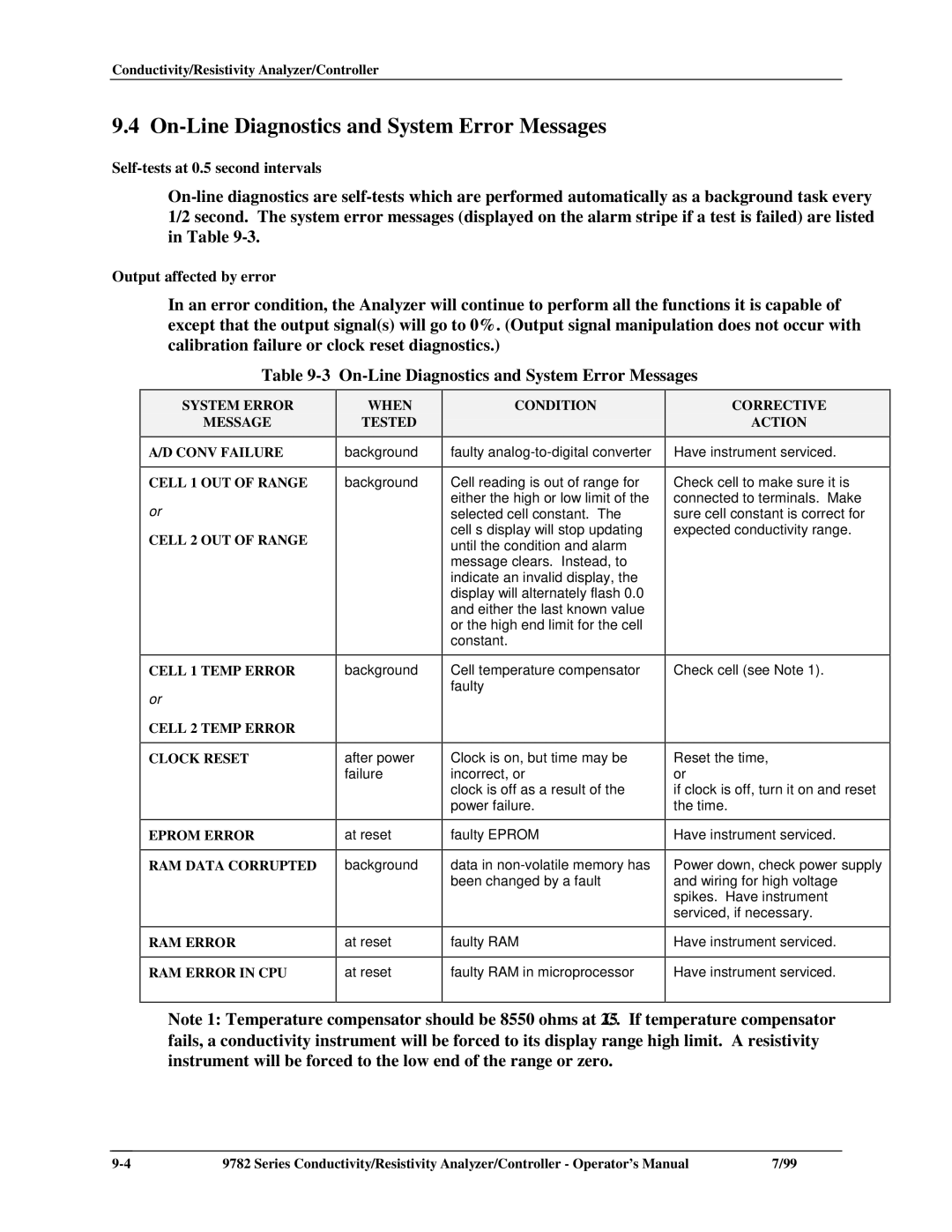
Table 9-3 On-Line Diagnostics and System Error Messages
SYSTEM ERROR
MESSAGE
A/D CONV FAILURE
CELL 1 OUT OF RANGE
or
CELL 2 OUT OF RANGE
CELL 1 TEMP ERROR
or
CELL 2 TEMP ERROR
CLOCK RESET
EPROM ERROR
RAM DATA CORRUPTED
RAM ERROR
RAM ERROR IN CPU
WHEN
TESTED
background
background
background
after power failure
at reset
background
at reset
at reset
CONDITION
faulty
Cell reading is out of range for either the high or low limit of the selected cell constant. The cell’s display will stop updating until the condition and alarm message clears. Instead, to indicate an invalid display, the display will alternately flash 0.0 and either the last known value or the high end limit for the cell constant.
Cell temperature compensator faulty
Clock is on, but time may be incorrect, or
clock is off as a result of the power failure.
faulty EPROM
data in
faulty RAM
faulty RAM in microprocessor
CORRECTIVE
ACTION
Have instrument serviced.
Check cell to make sure it is connected to terminals. Make sure cell constant is correct for expected conductivity range.
Check cell (see Note 1).
Reset the time, or
if clock is off, turn it on and reset the time.
Have instrument serviced.
Power down, check power supply and wiring for high voltage spikes. Have instrument serviced, if necessary.
Have instrument serviced.
Have instrument serviced.
Note 1: Temperature compensator should be 8550 ohms at 25 °C. If temperature compensator fails, a conductivity instrument will be forced to its display range high limit. A resistivity instrument will be forced to the low end of the range or zero.
9782 Series Conductivity/Resistivity Analyzer/Controller - Operator’s Manual | 7/99 |