Conductivity/Resistivity Analyzer/Controller
Step
11
12
Screen
DISPLAY RESOLUTION
RESOLUTION LOW
UOMuS
DIAGNOSTICS
PREV NEXT
SELECT CELL CONSTANT
C1 | 0.1 |
C2 | N/A |
DIAGNOSTICS
PREV NEXT
Action
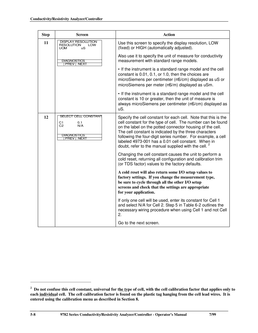
Use this screen to specify the display resolution, LOW (fixed) or HIGH (automatically adjusted).
Also use it to specify the unit of measure for conductivity measurement with standard range models.
∙If the instrument is a standard range model and the cell
constant is 0.01, 0.1, or 1.0, then the choices are microSiemens per centimeter (μS/cm) displayed as uS or microSiemens per meter (μS/m) displayed as uSm.
∙If the instrument is a standard range model and the cell
constant is 10 or greater, then the unit of measure is always microSiemens per centimeter (μS/cm) displayed as uS.
Specify the cell constant for each cell. Note that this is the cell constant for the type of cell. The number can be found on the label on the potted connector housing of the cell.
The cell constant is indicated by the three characters following the
Changing the cell constant causes the unit to perform a cold reset, returning all configuration and calibration trim (or TDS factor) values to the factory defaults.
A cold reset will also return some I/O setup values to factory settings. If you change the measurement type, be sure to cycle through all the other I/O setup screens and check that the settings are appropriate for your application.
If only one cell will be used, enter its constant for Cell 1 and select N/A for Cell 2. Step 5 in Table
Go to the next screen.
2Do not confuse this cell constant, universal for the type of cell, with the cell calibration factor that applies only to each individual cell. The cell calibration factor is found on the plastic tag hanging from the cell lead wires. It is entered using the calibration menu as described in Section 8.
9782 Series Conductivity/Resistivity Analyzer/Controller - Operator’s Manual | 7/99 |
