I/O Setup and System Configuration
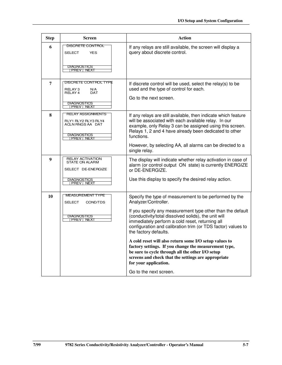
Step | Screen |
|
|
6DISCRETE CONTROL
SELECTYES
DIAGNOSTICS
PREV NEXT
7DISCRETE CONTROL TYPE
RELAY | 3 | N/A |
RELAY | 4 | DAT |
DIAGNOSTICS
PREV NEXT
8RELAY ASSIGNMENTS
RLY1 | RLY2 | RLY3 | RLY4 |
ACLN | RNGS | AA | DAT |
DIAGNOSTICS
PREV NEXT
9RELAY ACTIVATION STATE ON ALARM
SELECT
DIAGNOSTICS
PREV NEXT
10MEASUREMENT TYPE
SELECT COND/TDS
DIAGNOSTICS
PREV NEXT
Action
If any relays are still available, the screen will display a query about discrete control.
If discrete control will be used, select the relay(s) to be used and the type of control for each.
Go to the next screen.
If any relays are still available, then indicate which feature will be associated with each available relay. In our example, only Relay 3 can be assigned using this screen. Relays 1, 2 and 4 have already been dedicated to other functions.
However, by selecting AA, all alarms can be directed to a single relay.
The display will indicate whether relay activation in case of alarm (or control output “ON” state) is currently ENERGIZE or
Use this display to specify the desired relay action.
Specify the type of measurement to be performed by the Analyzer/Controller.
If you specify any measurement type other than the default (conductivity/total dissolved solids), the unit will immediately perform a cold reset, returning all configuration and calibration trim (or TDS factor) values to the factory defaults.
A cold reset will also return some I/O setup values to factory settings. If you change the measurement type, be sure to cycle through all the other I/O setup screens and check that the settings are appropriate for your application.
Go to the next screen.
7/99 | 9782 Series Conductivity/Resistivity Analyzer/Controller - Operator’s Manual |