Conductivity/Resistivity Analyzer/Controller |
|
|
|
|
|
|
| ||
|
|
|
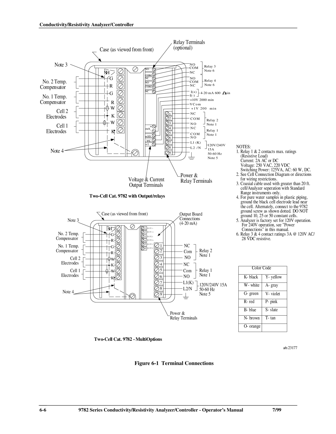
| Relay Terminals |
|
|
| ||
| Case (as viewed from front) |
| (optional) |
|
|
|
|
| |
|
|
|
|
|
|
|
| ||
Note 3 |
|
|
| NO |
| Relay 3 |
|
|
|
| SH | NO |
| COM |
| Note 6 |
|
|
|
|
|
| NC |
|
|
|
| ||
| COM |
|
|
|
|
|
| ||
| G |
| NO |
|
|
|
|
| |
No. 2 Temp. | NC |
|
| Relay 4 |
|
|
| ||
| NO |
| COM |
|
|
|
| ||
Compensator | R | COM |
| NC |
| Note 6 |
|
|
|
| I(+) |
|
|
|
|
| |||
No. 1 Temp. | G | NC |
| min |
|
| |||
|
|
|
| ||||||
|
|
|
|
|
|
|
| ||
|
|
| +10V 2000 min |
|
|
| |||
Compensator | R |
|
|
|
|
| |||
|
| VC om |
|
|
|
| |||
| W |
|
|
|
|
|
| ||
Cell 2 |
|
| +1V 200 m i n |
|
|
| |||
K |
| 1 | NC |
|
|
|
|
| |
Electrodes |
|
|
|
|
|
| |||
| 2 | C O M | Relay 2 |
|
|
| |||
| W |
| 3 | N O |
|
|
|
| |
Cell 1 | + |
| Note 1 |
|
|
| |||
| 4 | N C |
|
|
|
|
| ||
Electrodes | K | mA- |
| Relay 1 |
|
|
| ||
+10 | 5 | C O M | Note 1 |
|
|
| |||
|
| 6 | N O |
|
|
|
|
| |
|
| VC |
|
|
|
|
| ||
|
| 7 | L1 (K) |
|
|
|
| ||
|
| +1 | 120V/240V |
| NOTES: |
| |||
|
| 8 | L2 / N |
|
| ||||
Note 4 |
|
| 15A |
|
| ||||
|
| 9 |
|
|
| 1. Relay 1 & 2 contacts max. ratings | |||
|
|
|
|
| |||||
|
|
|
|
|
| (Resistive Load) | |||
|
|
|
|
|
| Note 5 |
| ||
|
|
|
|
|
|
| Current: 2A AC or DC | ||
|
|
|
|
|
|
|
| ||
|
|
|
|
|
|
|
| Voltage: 250 VAC, 220 VDC | |
|
|
|
|
|
|
|
| Switching Power: 125VA, AC: 60 W, DC. | |
|
| Voltage & Current | Power & |
|
|
| 2. See Cell Connection Diagram or directions | ||
|
| Relay Terminals |
| for wiring restrictions. | |||||
|
| Output Terminals |
|
|
|
| 3. Coaxial cable used with greater than 20 ft. | ||
|
|
|
|
|
|
|
| cell/Analyzer seperation with Standard | |
|
|
|
|
| Range instruments only. | ||||
|
|
|
|
| 4. For pure water samples in plastic piping, | ||||
|
|
|
|
|
|
|
| ground the black cell electrode lead near | |
|
|
|
|
|
|
|
| the cell. Alternately, connect to the 9782 | |
| Case (as viewed from front) |
| Output Board |
|
| ground screw as shown dotted. DO NOT | |||
|
|
|
| ground 10, 25 or 50 constant cells. | |||||
Note 3 |
|
|
| Connections |
|
| |||
|
|
|
|
| 5. Analyzer is factory set for 120V operation. | ||||
|
|
|
|
|
| ||||
|
|
|
|
|
|
| For 240V operation, see "Power | ||
| SH |
|
|
|
|
|
| ||
| 1 O U T 1 - |
|
|
|
|
| Connections" in this manual. | ||
No. 2 Temp. | G | 2 O U T 1 + |
|
|
|
|
| 6. Relay 3 & 4 contact ratings 3A @ 120V AC/ | |
3 O U T 2 - |
|
|
|
|
| ||||
Compensator |
|
|
|
|
|
| 28 VDC resistive. | ||
R | 4 O U T 2 + |
|
|
|
|
| |||
No. 1 Temp. | G | 5 O U T 3 - | 1 | NC |
|
|
|
|
|
6 O U T 3 + | Relay 2 |
|
|
| |||||
Compensator | R |
| 2 | Com |
|
|
| ||
Cell 2 | W |
| 3 | NO | Note 1 |
|
|
| |
|
|
|
|
|
| ||||
Electrodes | K |
| 4 | NC |
|
|
| Color Code | |
|
|
|
|
| |||||
Cell 1 | W |
| 5 | Com | Relay 1 |
| |||
|
|
|
| ||||||
Electrodes | K |
| 6 | NO | Note 1 |
| K- black | Y- yellow | |
|
|
| 7 | L1(K) | 120V/240V 15A | W- white | A- gray | ||
|
|
| 8 | L2/N | |||||
Note 4 |
|
|
| G- green | V- violet | ||||
|
| 9 |
| Note 5 |
| ||||
|
|
|
|
| |||||
|
|
| R- red | P- pink |
|
|
|
|
|
Power & | B- blue | S- slate | ||
|
| |||
Relay Terminals | N- brown | T- tan | ||
|
|
|
|
|
|
|
| O- orange |
|
a/n 23177
Figure 6-1 Terminal Connections
9782 Series Conductivity/Resistivity Analyzer/Controller - Operator’s Manual | 7/99 |