Unpacking, Preparation, and Mounting
Vertical Rear Pipe Mounting | LEGEND: | inches |
|
|
|
| ||||||||||||||||||
millimeters |
|
|
|
|
| 3.06 | ||||||||||||||||||
|
|
|
|
| 7.43 ±.070 |
|
|
|
|
|
|
|
|
|
|
|
|
|
|
|
| 77.80 | ||
|
|
|
|
|
|
|
|
|
|
|
|
|
|
|
| |||||||||
|
| 188.72 ±1.78 |
|
|
|
|
|
|
|
|
|
|
|
|
|
|
|
|
|
| ||||
|
|
|
|
|
|
|
|
|
|
|
|
|
|
|
|
|
|
|
|
|
|
|
|
|
|
|
|
|
|
|
|
|
|
|
|
|
|
|
|
|
|
|
|
|
|
|
|
|
|
|
|
|
|
|
|
|
|
|
|
|
|
|
|
|
|
|
|
|
|
|
|
|
|
|
![]()
![]()
![]() 1.00 IPS Pipe
1.00 IPS Pipe ![]() 25.40 (by customer)
25.40 (by customer)
Note 1: Do not exceed 80
7.68±.060
195.07 ±1.52
Top View
7.43 ±.070
188.72 ±1.781.50
38.10
Panel Mounting
into existing 7075, 7076, 7077, and 7078 series cutouts
|
|
|
|
|
|
|
|
|
|
|
|
|
|
|
|
|
|
|
|
|
|
|
|
|
|
|
|
|
|
|
|
|
|
|
|
|
|
|
|
| C |
|
|
|
|
| 3.00 | ||
|
| ||||||||
| L |
| 76.20 | ||||||
|
|
| |||||||
|
|
|
|
|
|
|
|
|
|
|
|
|
|
|
|
|
|
|
|
|
|
|
|
|
|
|
|
|
|
|
|
|
|
|
|
|
|
|
|
|
|
|
|
|
|
|
|
|
|
Four holes in bracket or 1/4 dia. mounting bolts (bolts by customer)
1.06±.025 26.92 ±0.64
.25 max.
6.35
Customer Panel
C
L6.43 ±0.70 163.32 ±1.78
6.27 ±.040
159.26 ±1.02
R.H. Side View
Wall Mounting
C
L
6.63
168.40
3.31
84.07
Panel Mounting
1.00±.025 25.40 ±0.64
C
L6.43 ±0.70 163.32 ±1.78
7.68±.060
195.07 ±1.52
.12 min. .37 max.
3.049.40
Customer Panel
6.27 ±.040
159.26 ±1.02
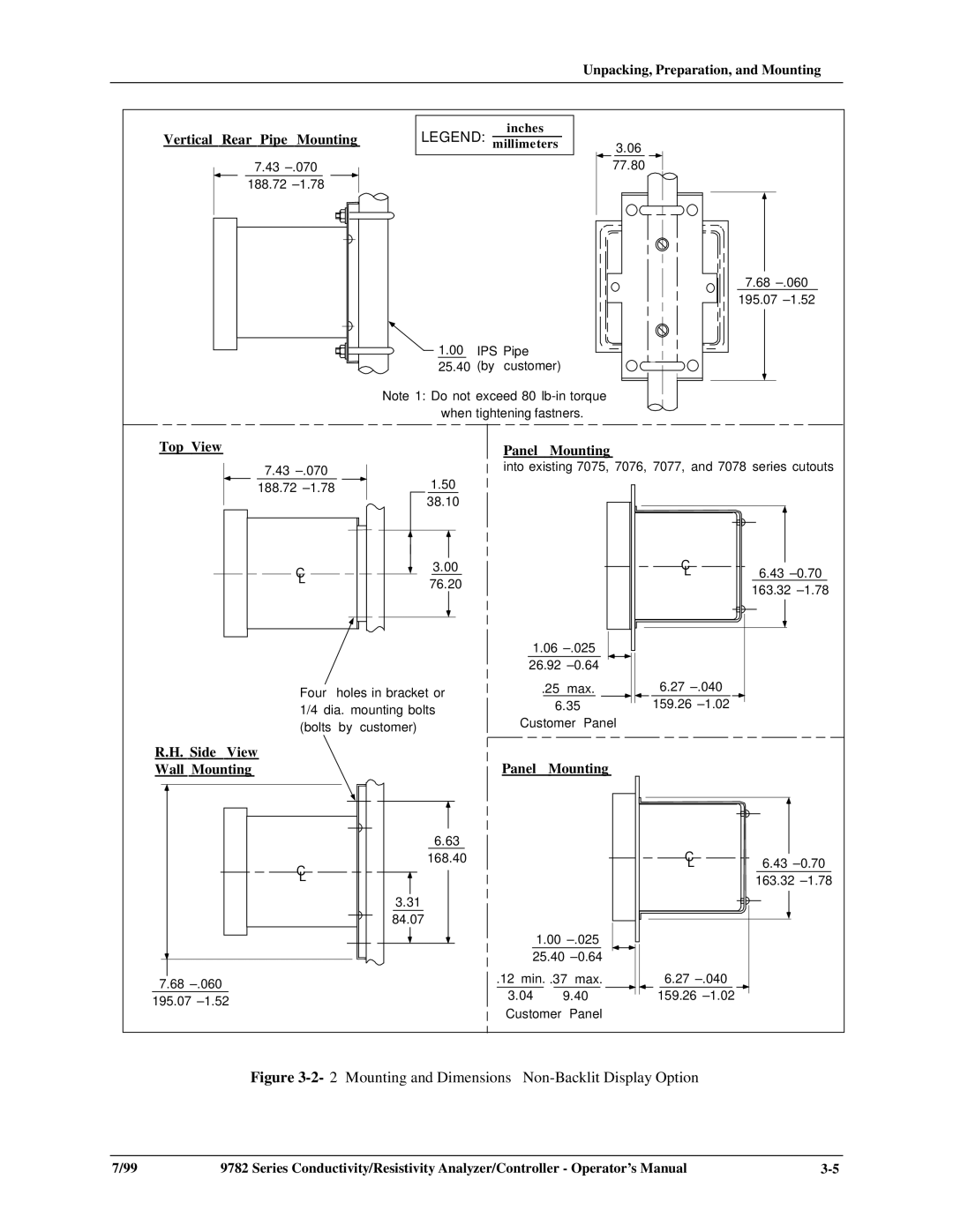
Figure 3-2-2 Mounting and Dimensions – Non-Backlit Display Option
7/99 | 9782 Series Conductivity/Resistivity Analyzer/Controller - Operator’s Manual |