Maintenance
Step | Screen |
|
|
8OUTPUT1 SPAN OUTPUT1 ZERO OUTPUT2 SPAN OUTPUT2 ZERO OUTPUT3 SPAN OUTPUT3 ZERO
DIAGNOSTICS
9SPAN CAL OUTPUT1
USE UP/DOWN ARROW
KEYS TO ADJUST
ENTER TO SAVE
DIAGNOSTICS
10OUTPUT CALIBRATION
SAVED
MENU TO EXIT
DIAGNOSTICS
11
12
13
14
Action
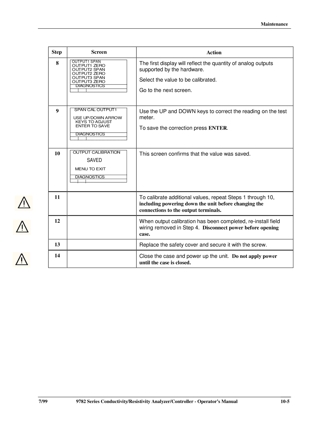
The first display will reflect the quantity of analog outputs supported by the hardware.
Select the value to be calibrated.
Go to the next screen.
Use the UP and DOWN keys to correct the reading on the test meter.
To save the correction press ENTER.
This screen confirms that the value was saved.
To calibrate additional values, repeat Steps 1 through 10, including powering down the unit before changing the connections to the output terminals.
When output calibration has been completed,
case.
Replace the safety cover and secure it with the screw.
Close the case and power up the unit. Do not apply power
until the case is closed.
7/99 | 9782 Series Conductivity/Resistivity Analyzer/Controller - Operator’s Manual |
