Microprocessor Board Switch Settings
Appendix C
Microprocessor Board Switch Settings
Introduction
The information in this appendix will not be needed for normal set up and operation of the 9782 Analyzer/Controller. It is included here for use during troubleshooting with the telephone assistance of the Honeywell Technical Assistance Center.
Location of switches
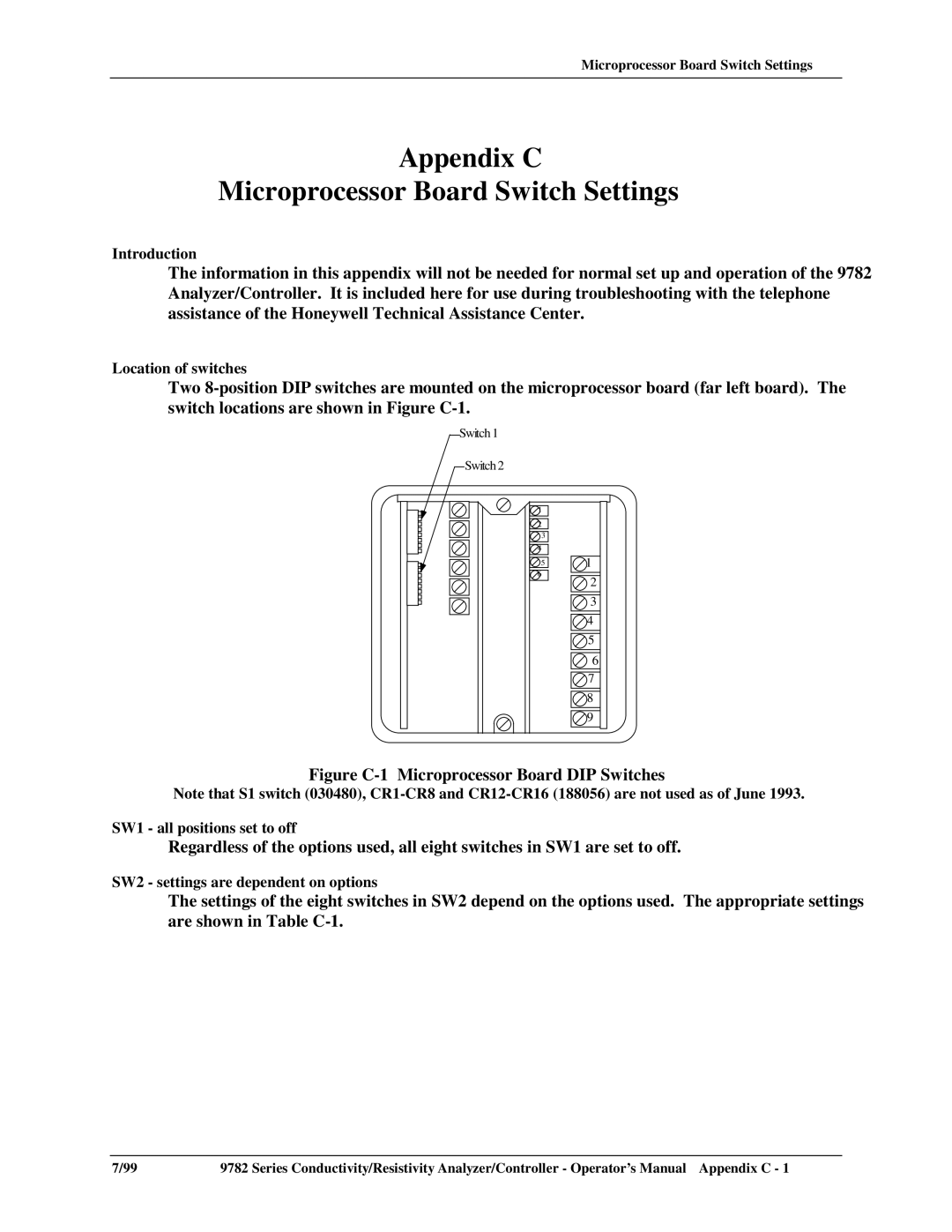
Two
Switch 1
Switch 2
![]()
![]() 1
1
![]()
![]() 2
2
![]()
![]() 3
3
![]()
![]() 4
4
![]()
![]() 5
5
![]()
![]() 6
6
![]()
![]() 1
1
![]()
![]() 2
2
![]()
![]() 3
3
![]()
![]() 4
4
![]()
![]() 5
5
![]()
![]() 6
6
![]()
![]() 7
7
![]()
![]() 8
8
![]()
![]() 9
9
Figure C-1 Microprocessor Board DIP Switches
Note that S1 switch (030480),
SW1 - all positions set to off
Regardless of the options used, all eight switches in SW1 are set to off.
SW2 - settings are dependent on options
The settings of the eight switches in SW2 depend on the options used. The appropriate settings are shown in Table
7/99 | 9782 Series Conductivity/Resistivity Analyzer/Controller - Operator’s Manual Appendix C - 1 |
