HP 800 Workstation
Copyright Information Warranty
Trademark Credits
About this guide
Guide topics
Iv About this guide
Table of contents
Restoring the operating system
System management
Replacing components
Customer self-repair Removing and installing components
Removing an optical disk drive from the optical drive bay
Diagnostics and troubleshooting
CPU
Configuring password security and resetting Cmos
Configuring RAID devices
Appendix a Connector pins
Appendix D Locating HP resources
Appendix B System board designators Appendix C Routine Care
235
System board architecture
Description
Topics
Memory technology
Addition features
Processor technology
Graphics
Workstation components
1Workstation component descriptions
Chassis components
Description
Front panel components
Item Symbol Description
2Front panel components
Rear panel components
3Rear panel components
Weight
Specifications
Physical characteristics
Chassis Dimensions
Temperature Humidity Altitude Shock Vibration
Environmental specifications
4HP Workstation environmental specifications
Non-operating
5Power supply source voltages
Power supply description
Power supply voltages
Source voltage Description
6Maximum current per rail
Power supply currents
Voltage rail
7Power supply specifications
Power supply specifications
Power consumption and heat dissipation
100-240 VAC 118 VAC
Resetting the power supply
System fans
Features
Ensuring proper ventilation
Topics
Energy Star Qualification
Enabling EUP compliance mode
EUP compliance mode
Accessibility
Disabling EUP compliance mode
Intel Turbo Boost Technology
Hyper-threading
HP Cool Tools
Setting up the operating system
Installing or upgrading device drivers
Setting up the Microsoft operating system
Transferring files and settings to your Windows workstation
Setting up Red Hat Enterprise Linux
Installing with the HP driver CD
Updating the workstation after first boot
Setting up Novell Sled
Installing and customizing Red Hat-enabled workstations
Upgrading the Bios
Determining current Bios
Upgrading Bios
Upgrading device drivers
Restore methods
Restoring the operating system
Ordering the RestorePlus! media
Ordering backup software Restoring Windows Vista
Restoring the operating system
Creating RestorePlus! media
Restoring Windows XP Professional
Creating HP Backup and Recovery Hpbr media
Using Hpbr
Creating restore media
Using RestorePlus
Using the recovery partition
Restoring Novell Sled
System management
Computer Setup F10 Utility
Computer Setup F10 functionality
Enww
Accessing the Computer Setup F10 Utility
1Computer Setup F10 Utility menu descriptions
Computer Setup F10 Utility menu
Heading Option Description
Disable 16 is the default
As a bootable device
Enabled by the operating system
MWAITE-AWARE OS
PCI VGA
HP Z800 Workstation PCI slots
HP Z600 PCI slots
HP Z400 Workstation PCI slots
Workstation management
Section topics
Initial workstation configuration and deployment
Installing a remote system
Replicating the setup
Copying a setup configuration to a single workstation
Copying a setup configuration to multiple workstations
Updating and managing software
Altiris Client Management Solutions
HP Client Manager Software
Proactive Change Notification
System Software Manager
Subscribers Choice
Remote ROM Flash
ROM Flash
HPQFlash F10 Flash
FailSafe Boot Block ROM
Recovering the workstation from Boot Block Recovery mode
Workstation security
Asset tracking
Feature Purpose How it is established
2Security features overview
Sata hard disk drive security
Using DriveLock
DriveLock applications
Enabling DriveLock
Select SecurityDriveLock Security
Password security
Establishing a power-on password using workstation setup
Entering a power-on password
Entering a setup password
Changing a power-on or setup password
3National keyboard delimiter characters
Deleting a power-on or setup password
National keyboard delimiter characters
Language Delimiter
Side access panel sensor Smart Cover Sensor optional
Clearing passwords
Side access panel key lock
4Side access panel sensor protection levels
Setting the Side access panel sensor protection level
Cable lock optional
Drive Protection System
Fault notification and recovery
ECC fault prediction
Thermal sensors
Dual-state power button
Changing the power button configuration
Replacing components
Enww
ESD information
Service considerations
Generating static
1Static shielding protection levels
Preventing ESD equipment damage
Personal grounding methods and equipment
Method Voltage
Grounding the work area
Recommended ESD prevention materials and equipment
Tools and software requirements
Cables and connectors
Special handling of components
Customer self-repair
Lithium coin cell battery
Hard drives
Removing and installing components
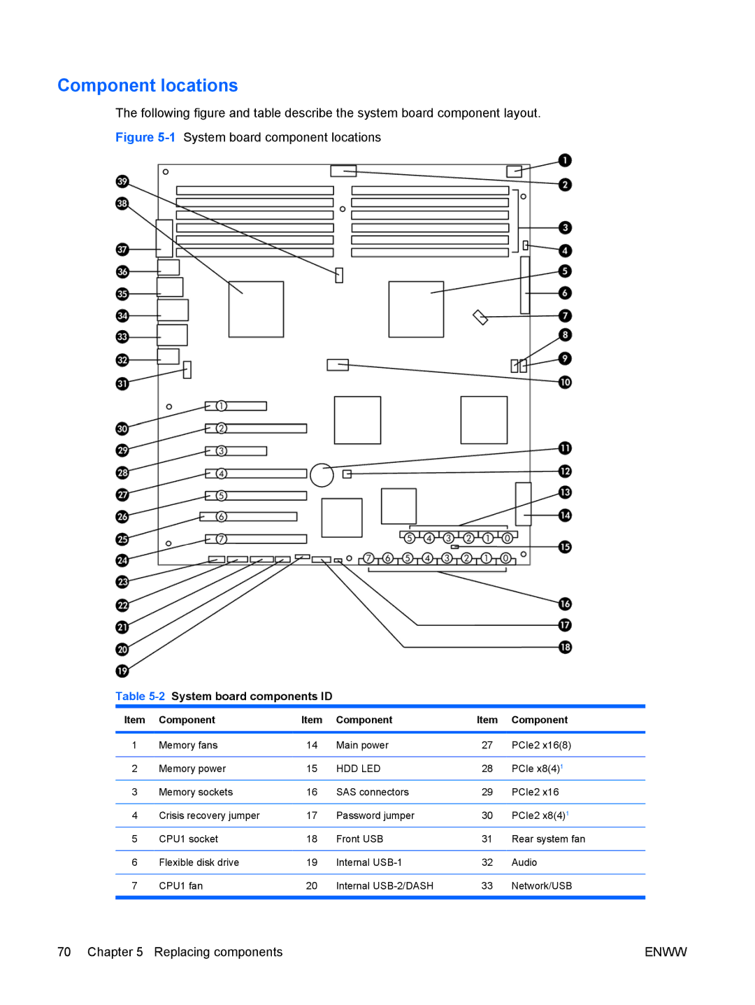
2System board components ID
Component locations
Component
Enww
Disassembly order
3Workstation component disassembly order
Predisassembly procedures
Cable lock optional
2Removing the cable lock Replacing components
Removing the side access panel
Side access panel
Installing the side access panel
Airflow guide
Removing the airflow guide
Expansion card support
Installing the airflow guide
Removing the expansion card support
8Removing the expansion card support Replacing components
Installing the expansion card support
9Installing the expansion card support
Removing the power supply
Power supply
Installing the right side panel
Right side panel
Speaker
Installing the power supply
Removing the speaker
Installing the speaker
Side access panel sensor optional
Removing the side access panel sensor
Installing the side access panel sensor
Power connections
4Workstation power connector description
Front bezel
Installing the front bezel
Removing the front bezel
Front panel I/O cable assembly
Removing the front panel I/O cable assembly
Enww
Installing the front panel I/O cable assembly
5Connecting the front panel I/O cable assembly cables
Enww
Power switch cable assembly
Removing the power switch cable assembly
Optical bay filler tray
Installing the power switch cable assembly
Removing a filler tray
22Removing a filler tray Replacing components
Installing a filler tray
23Installing a filler tray
Optical disk drive
Removing an optical disk drive from the optical drive bay
Enww
Installing an optical disk drive in the optical drive bay
Enww
Blu-ray movie playback compatibility and update
Blu-ray movie playback
Slot load optical disk drive optional
Removing the slot load optical disk drive
Enww
33Removing the optical disk drive from the carrier
Installing the slot load optical disk drive
Enww
Enww
Hard disk drive
Topic
Removing a hard disk drive from the hard drive bay
Installing a hard disk drive in the hard drive bay
Hard disk drive cable configuration
Installing a hard disk drive
Enww
Enww
Removing a hard disk drive from the slot load optical bay
Enww
50Removing the drive screws
Enww
Installing a hard disk drive in the slot load optical bay
53Fasten the hard drive in the carrier
Enww
Enww
Enww
Removing a hard disk drive from the optical drive bay
60Removing the drive from the ODD bay
Enww
Installing a hard disk drive in the optical drive bay
Enww
Installing dual SFF hard drives in the optical drive bay
Installing the hard drives
Enww
Configuring the cabling
Expansion card guide/front fan holder
Removing the expansion card guide/front fan holder
73Disconnecting the fan cable
Enww
Installing the expansion card guide/front fan holder
Removing the rear system fan assembly
System fans
Installing the rear system fan assembly
76Removing the rear system fans
Installing a second front system fan
Enww
Enww
Enww
Memory fans
Removing the memory fans
Installing the memory fans
Dimm installation guidelines Supported Dimm configurations
Memory
Bios errors and warnings
Removing a Dimm
Single processor configuration
Installing a Dimm
Required Dimm installation order
Dual processor configuration
Installing the Dimm
Enww
6Expansion card slot description and compatibility
Expansion card slot identification
Expansion card slot description
Slot Type Mechanical Electrical
75W 150W 175W
Power supply Graphics card maximum
75W 150W 175W 225W
Choosing an expansion card slot
PCIe card
Removing a PCIe card
Installing a PCIe card
Enww
PCI card
Removing a PCI card
Installing a PCI card
Enww
CPU heatsink
Removing the CPU heatsink
Enww
Installing the CPU heatsink
Enww
CPU
Removing a CPU
Installing a CPU
System board
Removing the system board
Enww
Installing the system board
Battery
Removing the battery
105Removing the battery Replacing components
Installing the battery
Product recycling
Diagnostics and troubleshooting
Calling technical support
Locating ID labels
Locating warranty information
Diagnosis guidelines
Diagnosis at startup
Troubleshooting checklist
Diagnosis during operation
Troubleshooting checklist
HP Help and Support Center
HP troubleshooting resources and tools
Troubleshooting a problem
Support
Product Change Notifications
Helpful hints
At startup
During operation
Customizing the monitor display
1Minor problems
Troubleshooting scenarios and solutions
Solving minor problems
Problem Cause Possible Solution
Testing power supply
Solving power supply problems
Problem Cause
2Power supply problems
Problem Cause Solution
3Diskette problems
Solving diskette problems
Select FilePropertiesTools
Boot in StorageBoot Order
Solving hard drive problems
4Hard drive problems
F1440
SecurityRestore Master Boot Record
Solving display problems
5Display problems
Select StartAll Programs AccessoriesSystem
Support.html
For this CD-ROM device
6Audio problems
Properties
Devices
7Printer problems
Solving printer problems
DIR C\ printer port
Self-troubleshooting with HP Vision Field Diagnostics
Overview
Downloading and accessing HP Vision Field Diagnostics
Locate HP Vision Field Diagnostics and select Download
User interface
Survey tab
Enww
Test tab
Enww
Status tab
Errors tab
History tab
Help tab
Downloading the latest diagnostic utility
Diagnostic codes and errors
Diagnostic LED and audible beep codes
8Diagnostic lights and audible codes
Activity Possible cause
Activity Possible cause Recommended action
Supply on page 80 for details
Red Power LED blinks nine
9LED color definitions
LED color definitions
LED state LED color System status
10POST error messages
Post error messages
Screen message Probable cause Recommended action
Is missing critical SPD information, or
If necessary, add a heatsink to the processor
Screen message Probable cause
Replace the processor with a compatible one
Enww
Maximum hard drive configurations
1Maximum hard drives
Configuring Sata RAID devices
Attaching Sata HDDs
Configuring system Bios
Creating RAID volumes
Deleting RAID volumes
Configuring SAS RAID devices
Supported configurations
SAS RAID 0 configuration
SAS RAID 1 configuration
SAS RAID 1E configuration
Configuring password security and resetting Cmos
Preparing to configure passwords
Clearing and Resetting the Cmos
Resetting the password jumper
Using the Cmos Button
Using the Computer Setup F10 Utility to Reset Cmos
Enww
Workstation PS/2 mouse Pin Signal
Workstation PS/2 keyboard Pin Signal
Workstation Ethernet Pin 10/100-MbSignal
Workstation IEEE-1394a Pin Signal
Workstation serial Pin Signal
Workstation USB Pin Signal
Pin Signal
Sata drive Pin Signal Data Cable Power Cable
217
Cable
SAS drive Segment Pin
Plug
Receptacles
Workstation VGA Pin Signal
DVI-I cable Pin Signal
Main power cable, P1
Display port
CPU power cable, P3 Pin Signal Color
Memory power cable, P2 Pin Color Signal
HDD bay power cable Pin Color Signal
850W 1110W
Graphics aux. power cables, P10, P11
Signal P11 Signal P10 Color Pin
V12-G V12-G1 V12-G2
Workstation front system fan 2, P94 Pin Signal
Workstation CPU fans, P70, P71 Pin Signal
Workstation front system fan 1, P93 Pin Signal
Workstation rear system fans, P8 Pin Signal
Workstation FDD Pin Signal
System board designators
Designator Silk screen Component
Appendix B System board designators
Cleaning the workstation case
General cleaning safety precautions
Cleaning the keyboard
Cleaning the monitor
Cleaning the mouse
Locating HP resources
Topic Location
Product information
Table D-1Product information
All Programs HP Cool Tools
Product support
Table D-2Product support
Table D-3Product documentation
Product documentation
Customer Bulletins, or Customer Notices
Product diagnostics
Table D-4Product diagnostics
TaskUse Tools to view...ToolsMy Computer
Product updates
Table D-5Product updates
InformationView general system information
Index
Appendices
Enww