INSTALLATION
Return to Section TOC
Return to Section TOC
Return to Section TOC
Return to Section TOC
Return to Master TOC
Return to Master TOC
Return to Master TOC
Return to Master TOC
LN-7 Connection Instructions
An
•Turn the Invertec power switch "off".
•Connect the K480 control cable from the
•Connect the electrode cable to the output terminal of the polarity required by electrode. Connect the work lead to the other terminal.
•Set the meter polarity switch on the front of the Invertec to coincide with wire feeder polarity used. The wire feeder will now display the welding voltage.
•If K480 is not available, see connection diagram S19404 for modification of K291 or K404
•If a remote control such as K857 is to be used with the
LN-10 Connection Instructions
An
•Turn the Invertec power switch "off"
•Connect the K1505 control cable from the
•Connect the electrode cable to the output terminal of polarity required by the electrode. Connect the work lead to the other terminal.
•Set the meter polarity switch on the front of the Invertec to coincide with wire feeder polarity used.
•See the
LN-742 Connection Instructions
An
•Turn the Invertec power switch "off"
•Either a K591 or a K593 Input cable assembly is required to connect the
•Connect the control cable from the
•Connect the electrode cable to the output terminal of the polarity required by electrode. Connect the work lead to the other terminal.
•Set the meter polarity switch on the front of the Invertec to coincide with wire feeder polarity used. The wire feeder will now display the welding volt- age.
•If a remote control such as K857 is to be used with the
Cobramatic Connection Instructions
A Cobramatic can only be used with the “Factory” & “Advanced Process” versions of the
•Turn the Invertec power switch "off"
•Connect the control cable from the Cobramatic to the
•Connect the electrode cable to the output terminal of the polarity required by electrode. Connect the work lead to the other terminal.
•Set the meter polarity switch on the front of the Invertec to coincide with wire feeder polarity used.
•If a remote control such as K857 is to be used with the Cobramatic, the remote can be connected directly to the
TIG Module K930-2
The TIG Module connects to the Factory and Advanced Process
The TIG Module can also be used with the
General Instructions for Connection of Wire Feeders to
Wire feeders other than those listed above may be used provided that the auxiliary power supply rating of the
REMOTE CONTROL OF INVERTEC
Remote Control K857, Hand Amptrol K963 and Foot Amptrol K870.
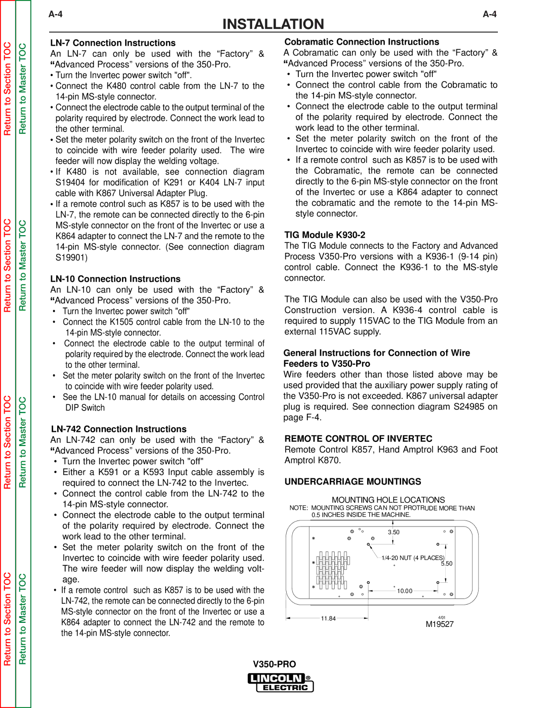
UNDERCARRIAGE MOUNTINGS
MOUNTING HOLE LOCATIONS
NOTE: MOUNTING SCREWS CAN NOT PROTRUDE MORE THAN
0.5INCHES INSIDE THE MACHINE.
3.50
![]() 1/4-20
1/4-20
10.00
11.84 | 4/01 |
M19527