Return to Section TOC
to Section TOC
Return to Master TOC
to Master TOC
TROUBLESHOOTING & REPAIR
MAIN SWITCH BOARD REMOVAL & REPLACEMENT (continued)
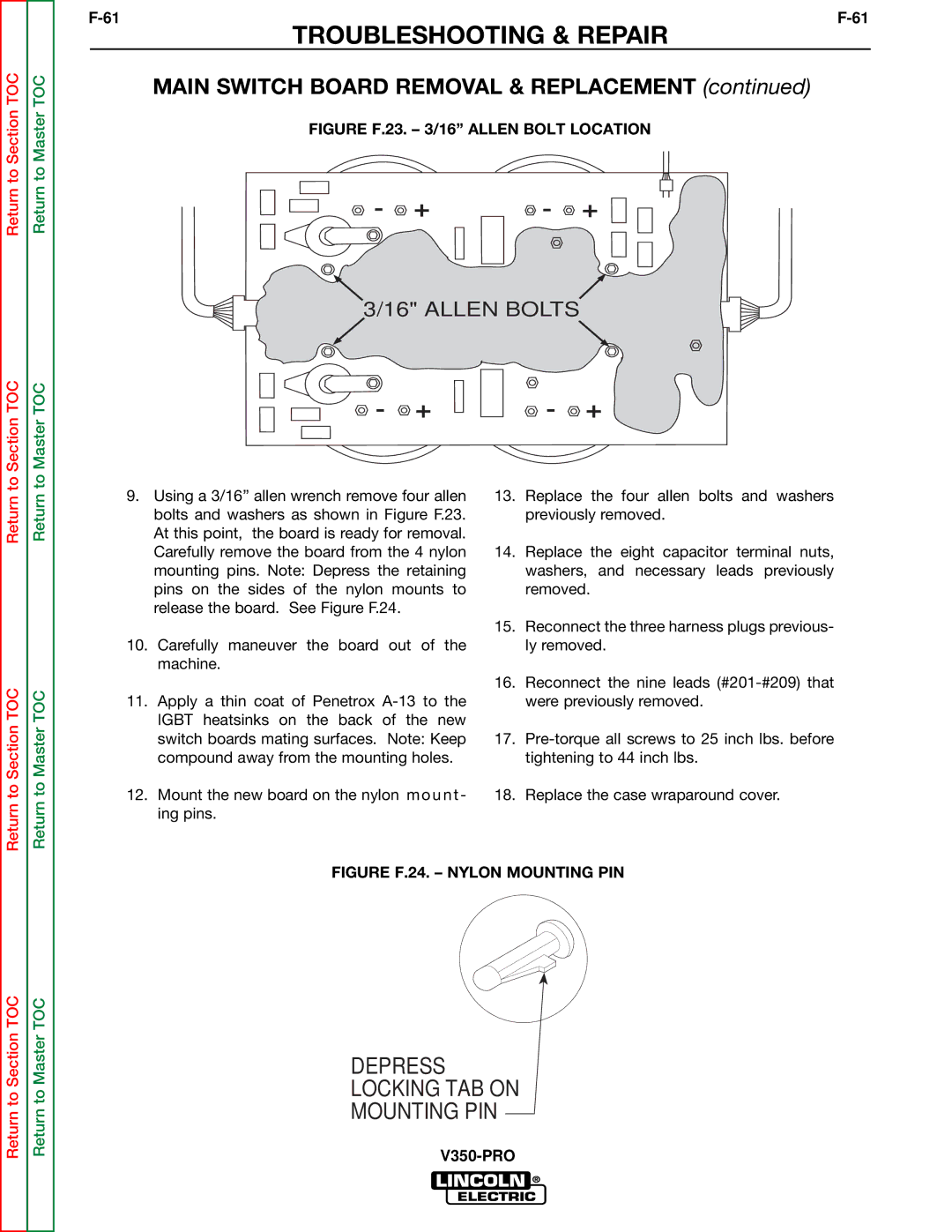
FIGURE F.23. – 3/16” ALLEN BOLT LOCATION
- + | - + |
3/16" ALLEN BOLTS 
- + | - + |
Return
Return to Section TOC
Return
Return to Master TOC
9.Using a 3/16” allen wrench remove four allen bolts and washers as shown in Figure F.23. At this point, the board is ready for removal. Carefully remove the board from the 4 nylon mounting pins. Note: Depress the retaining pins on the sides of the nylon mounts to release the board. See Figure F.24.
10.Carefully maneuver the board out of the machine.
11.Apply a thin coat of Penetrox
12.Mount the new board on the nylon mount - ing pins.
13.Replace the four allen bolts and washers previously removed.
14.Replace the eight capacitor terminal nuts, washers, and necessary leads previously removed.
15.Reconnect the three harness plugs previous- ly removed.
16.Reconnect the nine leads
17.
18.Replace the case wraparound cover.
Return to Section TOC
Return to Master TOC