Return to Section TOC
Return to Section TOC
Return to Master TOC
Return to Master TOC
| THEORY OF OPERATION | ||||||||
|
|
| |||||||
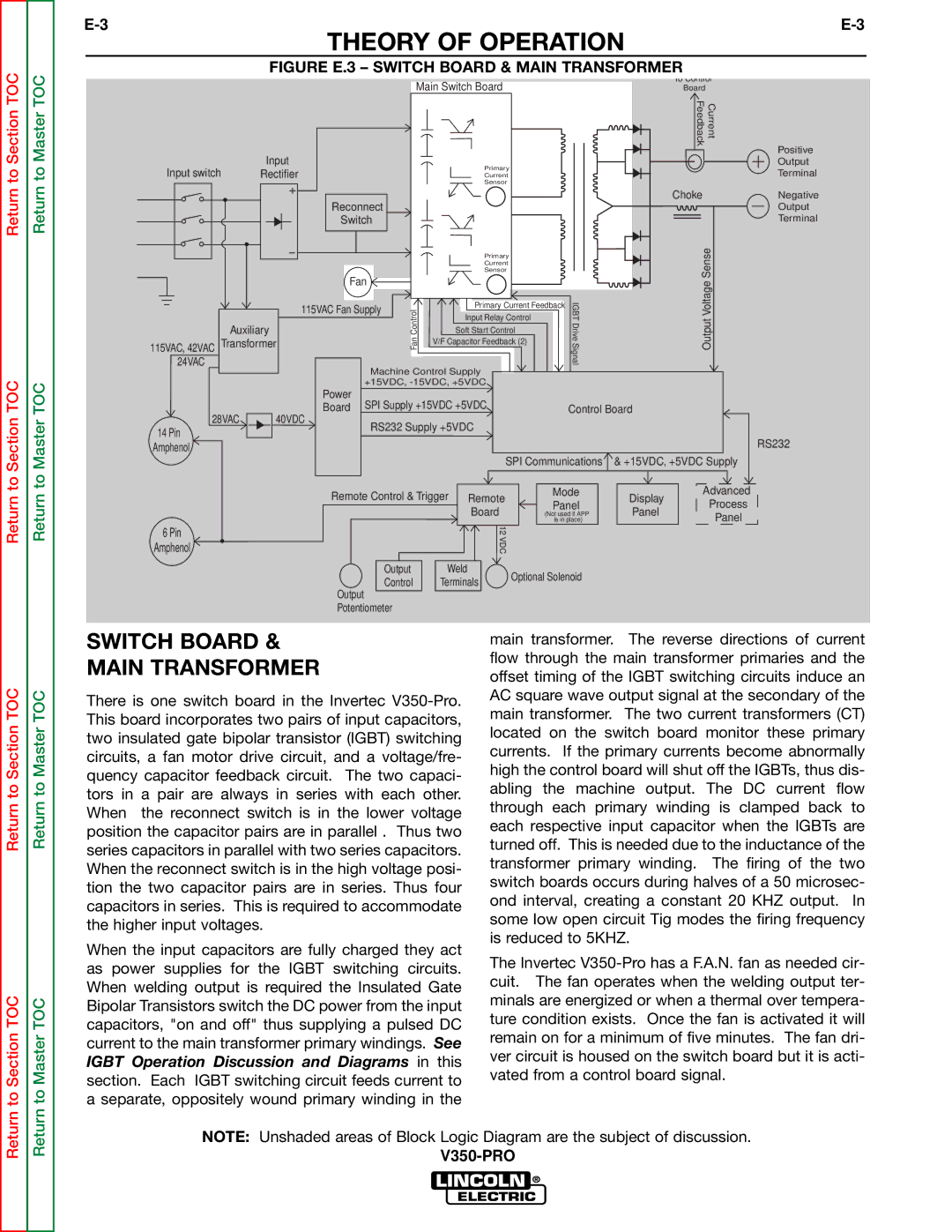
| FIGURE E.3 – SWITCH BOARD & MAIN TRANSFORMER |
| |||||||
|
|
| Main Switch Board |
|
|
| To Control | ||
|
|
|
|
|
| Board | urrentC | ||
|
|
|
|
|
|
|
| Feedback | |
| Input |
|
|
|
|
|
|
| Positive |
Input switch |
|
| Primary |
|
|
|
| Output | |
Rectifier |
|
|
|
|
|
| Terminal | ||
|
| Current |
|
|
|
| |||
|
|
|
| Sensor |
|
|
|
|
|
|
| Reconnect |
|
|
|
|
| Choke | Negative |
|
|
|
|
|
|
|
| Output | |
|
| Switch |
|
|
|
|
|
| Terminal |
|
|
|
| Primary |
|
|
| Sense | |
|
|
|
| Current |
|
|
|
|
|
|
|
|
| Sensor |
|
|
|
|
|
|
| Fan | ControlFan |
|
|
| IGBTDriveSignal | VoltageOutput | |
24VAC |
| 115VAC Fan Supply | Primary Current Feedback | ||||||
|
|
| Input Relay Control |
|
|
|
| ||
|
|
|
|
|
|
|
| ||
Auxiliary |
|
| Soft Start Control |
|
|
|
| ||
115VAC, 42VAC Transformer |
|
| V/F Capacitor Feedback (2) |
|
|
|
| ||
|
|
|
|
|
|
|
| ||
|
| Machine Control Supply |
|
|
|
|
| ||
|
| +15VDC, |
|
|
|
|
| ||
|
| Power |
|
|
|
|
|
|
|
28VAC |
| Board SPI Supply +15VDC +5VDC |
|
| Control Board |
| |||
40VDC |
|
|
|
|
|
|
| ||
14 Pin |
| RS232 Supply +5VDC |
|
|
|
|
| ||
|
|
|
|
|
|
|
| RS232 | |
Amphenol |
|
|
|
|
|
|
|
| |
|
|
|
| SPI Communications | & +15VDC, +5VDC Supply | ||||
|
| Remote Control & Trigger Remote |
| Mode | Advanced | ||||
|
|
| Panel | Display | Process | ||||
|
|
|
| Board |
| Panel | |||
|
|
|
|
| (Not used if APP | Panel | |||
|
|
|
|
|
| is in place) |
| ||
6 Pin |
|
|
| 12 |
|
|
|
|
|
|
|
| VDC |
|
|
|
|
| |
Amphenol |
|
|
|
|
|
|
|
| |
|
|
| Output | Weld | Optional Solenoid |
|
| ||
|
|
| Control | Terminals |
|
| |||
|
|
|
|
|
|
|
| ||
Output
Potentiometer
Return to Section TOC
to Section TOC
Return to Master TOC
to Master TOC
SWITCH BOARD &
MAIN TRANSFORMER
There is one switch board in the Invertec
When the input capacitors are fully charged they act as power supplies for the IGBT switching circuits. When welding output is required the Insulated Gate Bipolar Transistors switch the DC power from the input capacitors, "on and off" thus supplying a pulsed DC current to the main transformer primary windings. See IGBT Operation Discussion and Diagrams in this section. Each IGBT switching circuit feeds current to a separate, oppositely wound primary winding in the
main transformer. The reverse directions of current flow through the main transformer primaries and the offset timing of the IGBT switching circuits induce an AC square wave output signal at the secondary of the main transformer. The two current transformers (CT) located on the switch board monitor these primary currents. If the primary currents become abnormally high the control board will shut off the IGBTs, thus dis- abling the machine output. The DC current flow through each primary winding is clamped back to each respective input capacitor when the IGBTs are turned off. This is needed due to the inductance of the transformer primary winding. The firing of the two switch boards occurs during halves of a 50 microsec- ond interval, creating a constant 20 KHZ output. In some low open circuit Tig modes the firing frequency is reduced to 5KHZ.
The Invertec
Return
Return
NOTE: Unshaded areas of Block Logic Diagram are the subject of discussion.