ACCESSORIES
Return to Master TOC
Return to Master TOC
CONNECTION OF LINCOLN ELEC- TRIC WIRE FEEDERS
CONNECTION OF THE
1.Remove input power to the
2.Connect the electrode cable to the output terminal of polarity required by the electrode. Connect the work lead to the other terminal. Welding cable must be sized for current and duty cycle of the application.
3.Attach the single lead from the
4.Set the voltmeter switch to the electrode polarity chosen.
5.Set “CONTROL SELECT” to “REMOTE”.
6.Set the “MODE” to the
7.Set “WELD TERMINALS SELECT” to the “ON”
![]() CAUTION
CAUTION
position.
If you are using an
8.Set the “ARC CONTROL” to the “O” position and then adjust to suit.
Return to Section TOC
Return to Section TOC
Return to Section TOC
Return to Section TOC
Return to Master TOC
Return to Master TOC
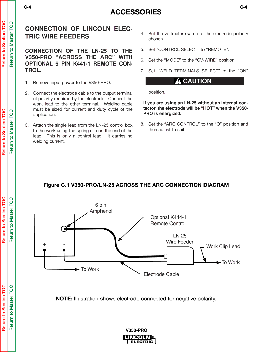
Figure C.1 V350-PRO/LN-25 ACROSS THE ARC CONNECTION DIAGRAM
6pin
Amphenol
|
| Optional | |
|
| Remote Control | |
|
| ||
+ | - | Wire Feeder | |
Work Clip Lead | |||
|
| ||
|
| To Work | |
|
| To Work | |
|
| Electrode Cable |
NOTE: Illustration shows electrode connected for negative polarity.