Return to Section TOC
Return to Master TOC
|
|
|
| |||||||||
|
|
| TROUBLESHOOTING & REPAIR | |||||||||
|
|
| AUXILIARY TRANSFORMER NO.1 TEST (continued) | |||||||||
|
|
|
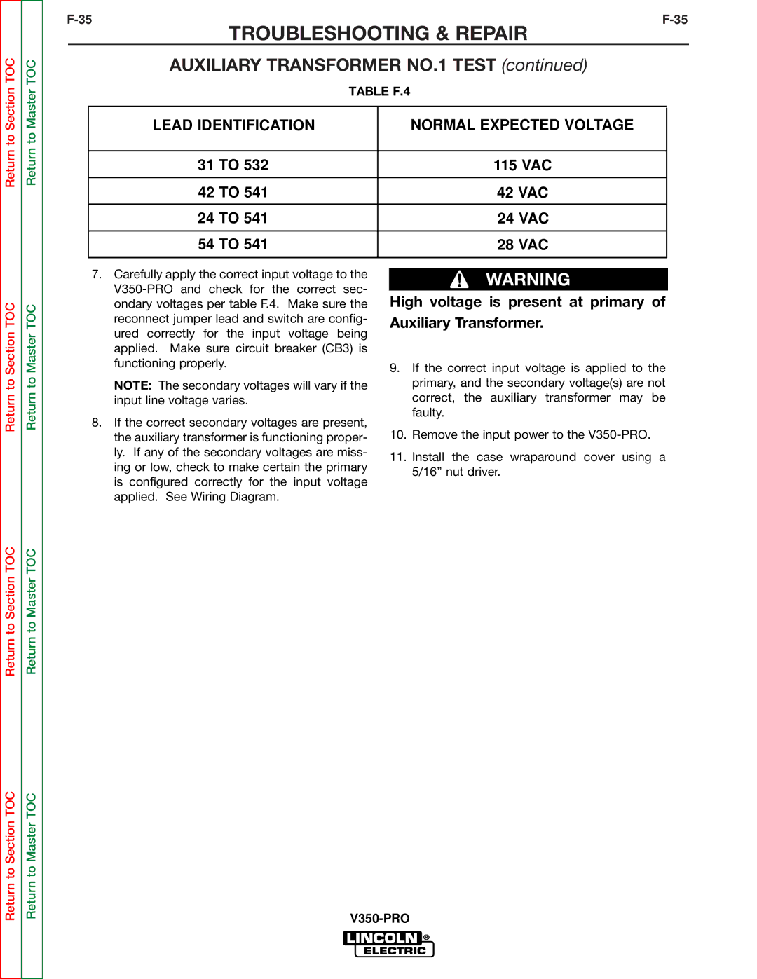
| TABLE F.4 | ||||||||
|
|
|
|
|
|
|
|
|
|
|
|
|
|
|
|
|
|
|
|
|
|
|
|
|
|
|
|
| LEAD IDENTIFICATION |
|
|
|
| NORMAL EXPECTED VOLTAGE |
| |||
|
|
|
|
|
|
|
|
|
|
|
|
|
|
|
|
|
|
|
|
|
|
|
|
|
|
|
|
|
|
|
|
|
|
|
|
|
|
|
|
|
| 31 TO 532 |
|
|
|
| |||||
|
|
|
|
|
|
| 115 VAC |
| ||||
|
|
|
|
|
|
|
|
|
|
|
|
|
|
|
|
|
|
|
|
|
|
|
|
|
|
|
|
|
|
|
|
|
|
|
|
|
| |
|
|
| 42 TO 541 |
|
|
|
| |||||
|
|
|
|
|
|
| 42 VAC |
| ||||
|
|
|
|
|
|
|
|
|
|
| ||
|
|
| 24 TO 541 |
|
|
|
| |||||
|
|
|
|
|
|
| 24 VAC |
| ||||
|
|
|
|
|
|
|
|
|
|
|
|
|
|
|
|
|
|
|
|
|
|
|
| ||
|
|
| 54 TO 541 |
|
|
|
| 28 VAC |
|
| ||
|
|
|
|
|
|
|
|
|
|
|
|
|
|
|
|
|
|
|
|
|
|
|
|
|
|
Return to Section TOC
Return to Section TOC
Return to Master TOC
Return to Master TOC
7.Carefully apply the correct input voltage to the
NOTE: The secondary voltages will vary if the input line voltage varies.
8.If the correct secondary voltages are present, the auxiliary transformer is functioning proper- ly. If any of the secondary voltages are miss- ing or low, check to make certain the primary is configured correctly for the input voltage applied. See Wiring Diagram.
WARNING
High voltage is present at primary of Auxiliary Transformer.
9.If the correct input voltage is applied to the primary, and the secondary voltage(s) are not correct, the auxiliary transformer may be faulty.
10.Remove the input power to the
11.Install the case wraparound cover using a 5/16” nut driver.
Return to Section TOC
Return to Master TOC