Return to Section TOC
Return to Section TOC
Return to Section TOC
Return to Section TOC
Return to Master TOC
Return to Master TOC
Return to Master TOC
Return to Master TOC
TROUBLESHOOTING AND REPAIR | ||||||
|
|
|
|
| ||
|
|
| RETEST AFTER REPAIR |
|
|
|
|
|
|
|
|
|
|
|
| Test | Required Action | Expected Results |
| |
|
| Steps |
|
|
| |
|
| Lft.display Rt. display |
| |||
|
|
|
| |||
|
|
|
|
|
| |
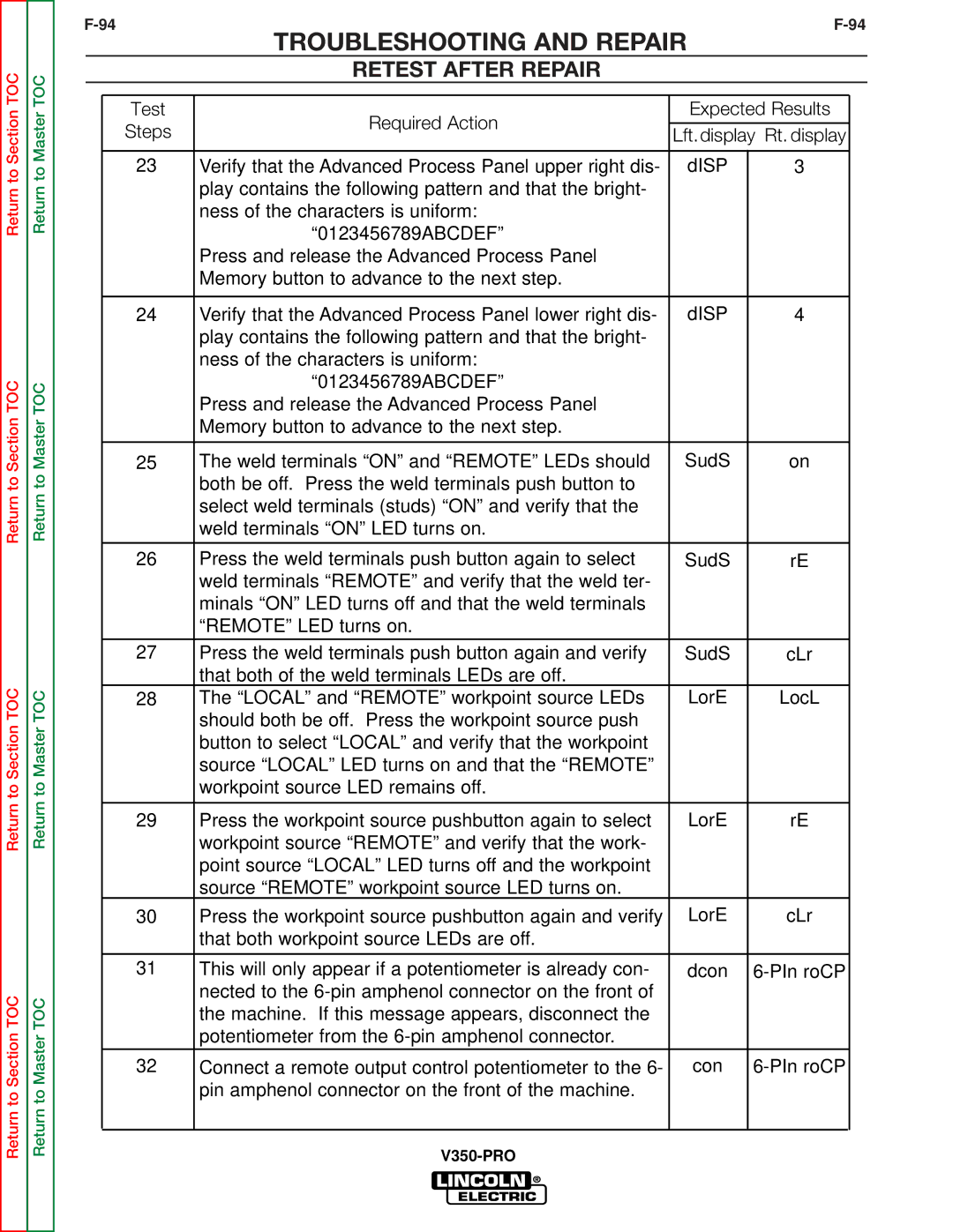
| 23 | Verify that the Advanced Process Panel upper right dis- | dISP | 3 |
| |
|
|
| play contains the following pattern and that the bright- |
|
|
|
|
|
| ness of the characters is uniform: |
|
|
|
|
|
| “0123456789ABCDEF” |
|
|
|
|
|
| Press and release the Advanced Process Panel |
|
|
|
|
|
| Memory button to advance to the next step. |
|
|
|
|
|
|
|
|
| |
| 24 | Verify that the Advanced Process Panel lower right dis- | dISP | 4 |
| |
|
|
| play contains the following pattern and that the bright- |
|
|
|
|
|
| ness of the characters is uniform: |
|
|
|
|
|
| “0123456789ABCDEF” |
|
|
|
|
|
| Press and release the Advanced Process Panel |
|
|
|
|
|
| Memory button to advance to the next step. |
|
|
|
|
|
|
|
|
| |
| 25 | The weld terminals “ON” and “REMOTE” LEDs should | SudS | on |
| |
|
|
| both be off. Press the weld terminals push button to |
|
|
|
|
|
| select weld terminals (studs) “ON” and verify that the |
|
|
|
|
|
| weld terminals “ON” LED turns on. |
|
|
|
|
|
|
|
|
| |
| 26 | Press the weld terminals push button again to select | SudS | rE |
| |
|
|
| weld terminals “REMOTE” and verify that the weld ter- |
|
|
|
|
|
| minals “ON” LED turns off and that the weld terminals |
|
|
|
|
|
| “REMOTE” LED turns on. |
|
|
|
|
|
|
|
|
| |
| 27 | Press the weld terminals push button again and verify | SudS | cLr |
| |
|
|
| that both of the weld terminals LEDs are off. |
|
|
|
| 28 | The “LOCAL” and “REMOTE” workpoint source LEDs | LorE | LocL |
| |
|
|
| should both be off. Press the workpoint source push |
|
|
|
|
|
| button to select “LOCAL” and verify that the workpoint |
|
|
|
|
|
| source “LOCAL” LED turns on and that the “REMOTE” |
|
|
|
|
|
| workpoint source LED remains off. |
|
|
|
|
|
|
|
|
| |
| 29 | Press the workpoint source pushbutton again to select | LorE | rE |
| |
|
|
| workpoint source “REMOTE” and verify that the work- |
|
|
|
|
|
| point source “LOCAL” LED turns off and the workpoint |
|
|
|
|
|
| source “REMOTE” workpoint source LED turns on. |
|
|
|
| 30 | Press the workpoint source pushbutton again and verify | LorE | cLr |
| |
|
|
| that both workpoint source LEDs are off. |
|
|
|
|
|
|
|
|
| |
| 31 | This will only appear if a potentiometer is already con- | dcon |
| ||
|
|
| nected to the |
|
|
|
|
|
| the machine. If this message appears, disconnect the |
|
|
|
|
|
| potentiometer from the |
|
|
|
|
|
|
|
|
| |
| 32 | Connect a remote output control potentiometer to the 6- | con |
| ||
|
|
| pin amphenol connector on the front of the machine. |
|
|
|
|
|
|
|
|
|
|
|
|
|
|
|
|
|