Return to Section TOC
Return to Section TOC
Section TOC
Return to Master TOC
Return to Master TOC
Master TOC
TROUBLESHOOTING & REPAIR
DISPLAY BOARD REMOVAL & REPLACEMENT (continued)
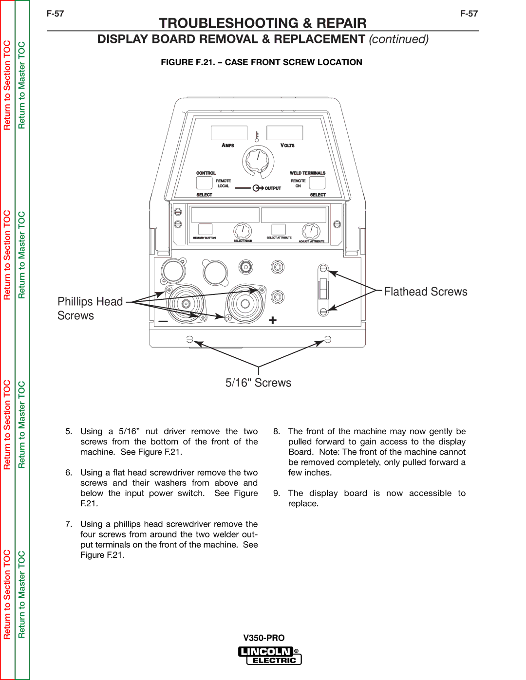
FIGURE F.21. – CASE FRONT SCREW LOCATION
AMPS | VOLTS | |
CONTROL |
| WELD TERMINALS |
REMOTE |
| REMOTE |
LOCAL | OUTPUT | ON |
|
| |
SELECT | SELECT |
MEMORY BUTTON | SELECT ATTRIBUTE |
SELECT KNOB | ADJUST ATTRIBUTE |
Phillips Head |
| Flathead Screws |
_ |
| |
Screws | + | |
|
|
5/16" Screws
Return to
Return to Section TOC
Return to
Return to Master TOC
5.Using a 5/16” nut driver remove the two screws from the bottom of the front of the machine. See Figure F.21.
6.Using a flat head screwdriver remove the two screws and their washers from above and below the input power switch. See Figure F.21.
7.Using a phillips head screwdriver remove the four screws from around the two welder out- put terminals on the front of the machine. See Figure F.21.
8.The front of the machine may now gently be pulled forward to gain access to the display Board. Note: The front of the machine cannot be removed completely, only pulled forward a few inches.
9.The display board is now accessible to replace.