Return to Section TOC
Return to Master TOC
TROUBLESHOOTING & REPAIR
CONTROL BOARD REMOVAL AND REPLACEMENT (continued)
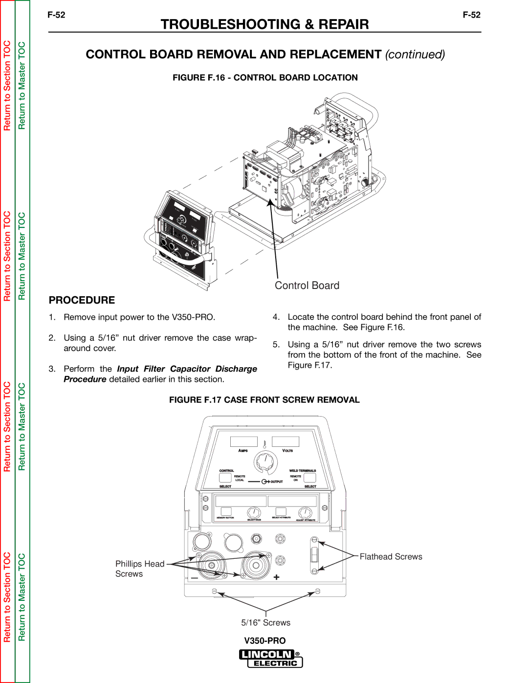
FIGURE F.16 - CONTROL BOARD LOCATION
Return to Section TOC
Return to Master TOC
| A | AMPS |
|
|
|
|
|
|
|
|
|
|
|
|
|
|
|
|
|
| |
|
|
|
|
|
|
|
| V | VOLTS |
|
|
|
|
|
|
|
|
|
|
| |
STICKTAW7018 |
| A |
|
|
| WELD |
|
| ||
| OUTPUT |
|
|
| ||||||
CC- |
|
|
|
|
|
|
|
|
|
|
|
|
|
|
|
|
| TERMINALS | |||
CV- |
|
|
|
|
|
|
|
| ||
TIG G | 6010 |
|
|
|
|
|
|
|
|
|
|
|
| HOT ST |
|
|
|
|
|
| |
FLUX | CORED |
| 4 | ART |
| SELECT |
| |||
|
| 5 |
|
| ||||||
| SELECT | 3 |
| 6 |
| ARC CO | NTROL |
| ||
WARNING | 2 |
|
|
|
| |||||
|
| 1 |
|
| 7 |
|
|
|
| |
|
|
|
|
|
|
|
| - |
|
|
|
|
|
| 0 |
| 8 | 2 | 0 |
| |
| REMOTE |
|
|
| 10 | 9 |
| +2 |
| |
|
|
|
|
|
|
|
|
| +4 | |
|
|
|
|
|
|
|
|
| +6 | |
|
|
|
|
|
|
|
| SOFT | +10 | +8 |
|
|
|
|
|
|
|
|
| CRISP | |
|
|
|
|
|
|
|
|
| POWER | |
|
|
|
|
|
| ON |
|
|
|
|
|
|
|
|
|
| OFF |
|
|
|
|
PROCEDURE
1.Remove input power to the
2.Using a 5/16” nut driver remove the case wrap- around cover.
3.Perform the Input Filter Capacitor Discharge Procedure detailed earlier in this section.
Control Board
4.Locate the control board behind the front panel of the machine. See Figure F.16.
5.Using a 5/16” nut driver remove the two screws from the bottom of the front of the machine. See Figure F.17.
Return to Section TOC
Return to Section TOC
Return to Master TOC
Return to Master TOC
FIGURE F.17 CASE FRONT SCREW REMOVAL
AMPS | VOLTS | |
CONTROL |
| WELD TERMINALS |
REMOTE |
| REMOTE |
LOCAL | OUTPUT | ON |
|
| |
SELECT | SELECT |
MEMORY BUTTON | SELECT ATTRIBUTE |
SELECT KNOB | ADJUST ATTRIBUTE |
Phillips Head |
| Flathead Screws |
_ |
| |
Screws | + | |
|
|
5/16" Screws