Return to Master TOC
Return to Master TOC
Return to Master TOC
Return to Master TOC
Section
TABLE OF CONTENTS
-THEORY OF OPERATION SECTION-
Theory of Operation | Section E |
General Description | |
Input Line Voltage, Auxiliary Transformer and Precharge | |
Switch Board and Main Transformer | |
Power board, Control Board, and SPI Communications | |
Output Rectifier and Choke | |
Thermal Protection | |
Protection Circuits | |
Over current Protection | |
Under/Over Voltage Protection | |
Insulated Gate Bipolar Transistor (IGBT) Operation | |
Pulse Width Modulation | |
Minimum/Maximum Output |
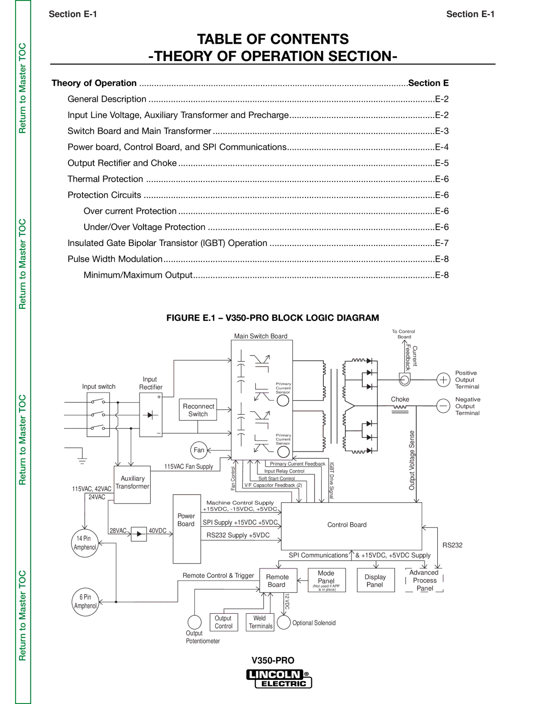
FIGURE E.1 – V350-PRO BLOCK LOGIC DIAGRAM
|
|
| Main Switch Board |
|
|
| To Control | |||
|
|
|
|
|
| Board |
| |||
|
|
|
|
|
|
|
|
| Feedback | Current |
| Input |
|
|
|
|
|
|
|
| Positive |
Input switch |
|
|
| Primary |
|
|
|
| Output | |
Rectifier |
|
|
|
|
|
|
| Terminal | ||
|
|
| Current |
|
|
|
| |||
|
|
|
|
| Sensor |
|
|
|
|
|
|
| Reconnect |
|
|
|
|
|
| Choke | Negative |
|
|
|
|
|
|
|
|
| Output | |
|
| Switch |
|
|
|
|
|
|
| Terminal |
|
|
|
|
| Primary |
|
|
| Sense | |
|
|
|
|
| Current |
|
|
|
|
|
|
|
|
|
| Sensor |
|
|
|
|
|
|
| Fan | ControlanF |
|
|
|
| IGBTDriveSignal | VoltageOutput | |
24VAC |
| 115VAC Fan Supply |
| Primary Current Feedback | ||||||
|
|
|
|
|
|
| ||||
|
|
|
| Input Relay Control |
|
|
|
| ||
|
|
|
|
|
|
|
|
| ||
Auxiliary |
|
|
| Soft Start Control |
|
|
|
| ||
115VAC, 42VAC Transformer |
|
| V/F Capacitor Feedback (2) |
|
|
|
| |||
|
|
|
|
|
|
|
|
| ||
|
| Machine Control Supply |
|
|
|
|
| |||
|
| +15VDC, |
|
|
|
|
| |||
|
| Power |
|
|
|
|
|
|
|
|
|
| Board SPI Supply +15VDC +5VDC |
|
| Control Board |
| ||||
28VAC | 40VDC |
|
|
|
|
|
|
|
| |
14 Pin |
| RS232 Supply +5VDC |
|
|
|
|
| |||
|
|
|
|
|
|
|
|
| RS232 | |
Amphenol |
|
|
|
|
|
|
|
|
| |
|
|
|
|
| SPI Communications | & +15VDC, +5VDC Supply | ||||
|
| Remote Control & Trigger | Remote |
| Mode | Advanced | ||||
|
|
| Panel | Display | Process | |||||
|
|
|
|
| Board |
| Panel | |||
|
|
|
|
|
| (Not used if APP | Panel | |||
|
|
|
|
|
|
| is in place) |
| ||
6 Pin |
|
|
|
| 12 |
|
|
|
|
|
|
|
|
| VDC |
|
|
|
|
| |
Amphenol |
|
|
|
|
|
|
|
|
| |
|
|
| Output | Weld | Optional Solenoid |
|
| |||
|
|
| Control | Terminals |
|
| ||||
|
| Output |
|
|
|
|
| |||
|
|
|
|
|
|
|
|
|
| |
|
| Potentiometer |
|
|
|
|
|
|
| |
|
|
|
|
|
|
|
| |||