Return to Section TOC
Return to Section TOC
Return to Section TOC
Return to Section TOC
Return to Master TOC
Return to Master TOC
Return to Master TOC
Return to Master TOC
TROUBLESHOOTING AND REPAIR
RETEST AFTER REPAIR
Retest a machine:
If it is rejected under test for any reason that requires you to remove any part which could affect the machine’s electrical characteristics.
If you repair or replace any electrical components:
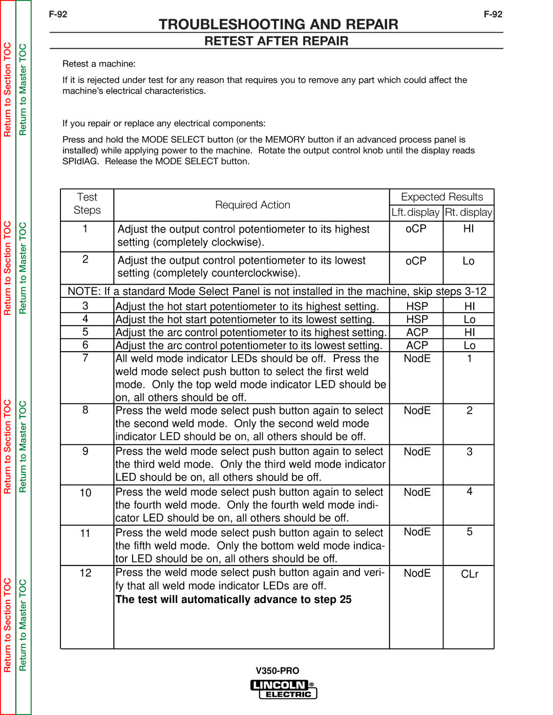
Press and hold the MODE SELECT button (or the MEMORY button if an advanced process panel is installed) while applying power to the machine. Rotate the output control knob until the display reads SPIdIAG. Release the MODE SELECT button.
Test | Required Action | Expected Results | |||
Steps |
|
|
| ||
Lft.display | Rt. display | ||||
| |||||
|
|
|
|
| |
1 | Adjust the output control potentiometer to its highest | oCP | HI | ||
| setting (completely clockwise). |
|
|
| |
|
|
|
|
| |
2 | Adjust the output control potentiometer to its lowest | oCP | Lo | ||
| setting (completely counterclockwise). |
|
|
| |
|
|
|
|
| |
NOTE: If a standard Mode Select Panel is not installed in the machine, skip steps
3 | Adjust the hot start potentiometer to its highest setting. | HSP | HI |
|
4 | Adjust the hot start potentiometer to its lowest setting. | HSP | Lo |
|
5 | Adjust the arc control potentiometer to its highest setting. | ACP | HI |
|
6 | Adjust the arc control potentiometer to its lowest setting. | ACP | Lo |
|
7 | All weld mode indicator LEDs should be off. Press the | NodE | 1 |
|
| weld mode select push button to select the first weld |
|
|
|
| mode. Only the top weld mode indicator LED should be |
|
|
|
| on, all others should be off. |
|
|
|
8 | Press the weld mode select push button again to select | NodE | 2 |
|
| the second weld mode. Only the second weld mode |
|
|
|
| indicator LED should be on, all others should be off. |
|
|
|
|
|
|
|
|
9 | Press the weld mode select push button again to select | NodE | 3 |
|
| the third weld mode. Only the third weld mode indicator |
|
|
|
| LED should be on, all others should be off. |
|
|
|
10 | Press the weld mode select push button again to select | NodE | 4 |
|
| the fourth weld mode. Only the fourth weld mode indi- |
|
|
|
| cator LED should be on, all others should be off. |
|
|
|
11 | Press the weld mode select push button again to select | NodE | 5 |
|
| the fifth weld mode. Only the bottom weld mode indica- |
|
|
|
| tor LED should be on, all others should be off. |
|
|
|
12 | Press the weld mode select push button again and veri- | NodE | CLr |
|
| fy that all weld mode indicator LEDs are off. |
|
|
|
| The test will automatically advance to step 25 |
|
|
|
|
|
|
|
|