ACCESSORIES
CONNECTION OF THE
NOTE: AN
1.Remove input power to the
2.Connect the electrode cable to the output terminal of polarity required by the electrode. Connect the work lead to the other terminal. Welding cable must be sized for current and duty cycle of the application.
3.Attach the single lead from the
4.Set the voltmeter switch to the electrode polarity chosen.
6.Set the “MODE” to the
7.Set “WELD TERMINALS SELECT” to the “REMOTE” position.
8.Set the “ARC CONTROL” to the “O” position and then adjust to suit.
9.Connect the K432 remote control cable to the LN- 25.
10.Connect the K876 adapter to the K432 and to the 24/42VAC
11.Adjust the wire feed speed and voltage at the LN- 25.
NOTE: See Figure C.4 for connection Using K867 adapter.
Return
5. Set “CONTROL SELECT” to “REMOTE”.
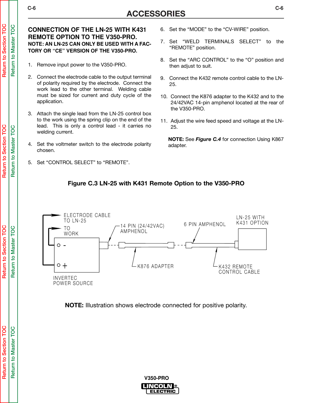
Figure C.3 LN-25 with K431 Remote Option to the V350-PRO
Return to Section TOC
Return to Section TOC
Return to Section TOC
Return to Master TOC
E L E C T R O D E C A B L E
T O L N - 2 5
T O
W O R K
-
+
I N V E R T E C
P O W E R S O U R C E
1 4 P I N ( 2 4 / 4 2 V A C )
A M P H E N O L
K 8 7 6 A D A P T E R
| L N - 2 5 W I T H |
6 P I N A M P H E N O L | K 4 3 1 O P T I O N |
|
K 4 3 2 R E M O T E
C O N T R O L C A B L E
Return to Section TOC
Return to Master TOC
NOTE: Illustration shows electrode connected for positive polarity.