TOC
TOC
TROUBLESHOOTING AND REPAIR
FAN CONTROL AND MOTOR TEST (continued)
Return to Section
Return to Section TOC
Return to Master
Return to Master TOC
7.If the 115VAC is low or not present check cir- cuit breaker CB2 located on the front panel. If the circuit breaker is OK, perform The Auxiliary Transformer Test. Check plug J22, circuit breaker CB2 and associated leads for loose or faulty connections. See the Wiring Diagram.
8.Energize the weld output terminals (Select Weld Terminals ON) and carefully check for 115VAC at plug J22
PRESENT AT THE SWITCH BOARD.
9.If the 115VAC is NOT present in the previous step then proceed to the fan control test.
FAN CONTROL TEST PROCEDURE
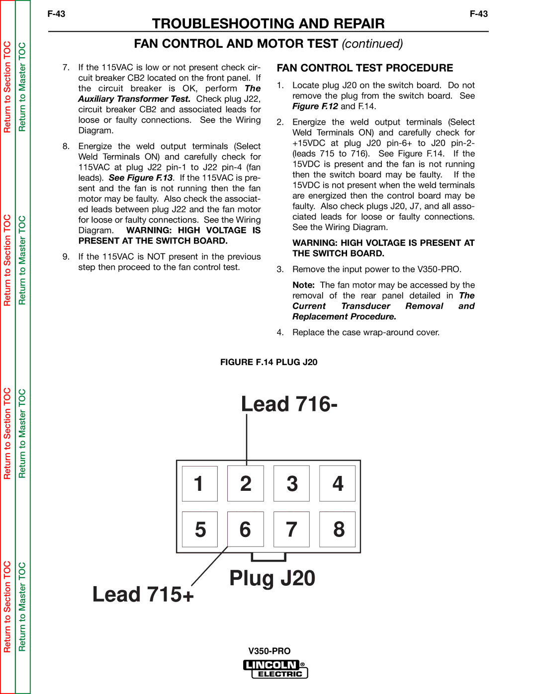
1.Locate plug J20 on the switch board. Do not remove the plug from the switch board. See Figure F.12 and F.14.
2.Energize the weld output terminals (Select Weld Terminals ON) and carefully check for +15VDC at plug J20
WARNING: HIGH VOLTAGE IS PRESENT AT THE SWITCH BOARD.
3.Remove the input power to the
Note: The fan motor may be accessed by the removal of the rear panel detailed in The
Current Transducer Removal and Replacement Procedure.
4.Replace the case
Return to Section TOC
Return to Section TOC
Return to Master TOC
Return to Master TOC
FIGURE F.14 PLUG J20
Lead 716-
1 | 2 | 3 | 4 |
5 | 6 | 7 | 8 |