Return to Section TOC
Return to Section TOC
Return to Master TOC
Return to Master TOC
TROUBLESHOOTING & REPAIR
ADVANCED PROCESS PANEL
REMOVAL AND REPLACEMENT (continued)
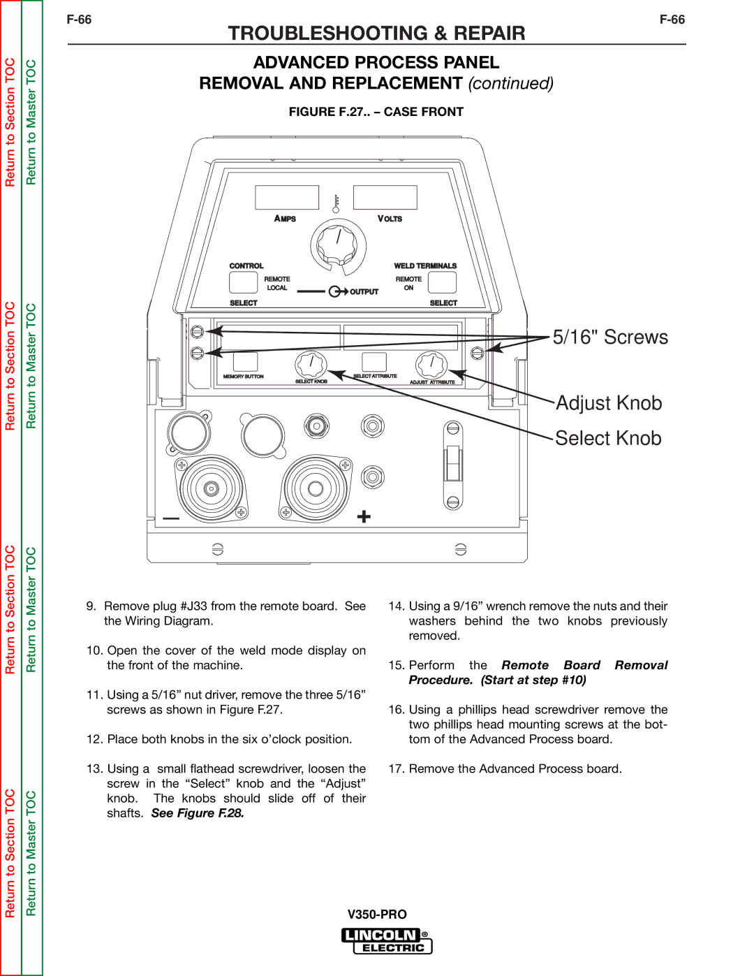
FIGURE F.27.. – CASE FRONT
AMPS | VOLTS | |
CONTROL |
| WELD TERMINALS |
REMOTE |
| REMOTE |
LOCAL | OUTPUT | ON |
|
| |
SELECT | SELECT |
| 5/16" Screws |
MEMORY BUTTON | SELECT ATTRIBUTE |
SELECT KNOB | ADJUST ATTRIBUTE |
| Adjust Knob |
| Select Knob |
_
 +
+
Return to Section TOC
Return to Section TOC
Return to Master TOC
Return to Master TOC
9.Remove plug #J33 from the remote board. See the Wiring Diagram.
10.Open the cover of the weld mode display on the front of the machine.
11.Using a 5/16” nut driver, remove the three 5/16” screws as shown in Figure F.27.
12.Place both knobs in the six o’clock position.
13.Using a small flathead screwdriver, loosen the screw in the “Select” knob and the “Adjust” knob. The knobs should slide off of their shafts. See Figure F.28.
14.Using a 9/16” wrench remove the nuts and their washers behind the two knobs previously removed.
15.Perform the Remote Board Removal
Procedure. (Start at step #10)
16.Using a phillips head screwdriver remove the two phillips head mounting screws at the bot- tom of the Advanced Process board.
17.Remove the Advanced Process board.