Using the EISA Configuration Utility
4.Select “Step 4: Examine switches or print report,” and press Enter to display the screen as shown in the figure below.
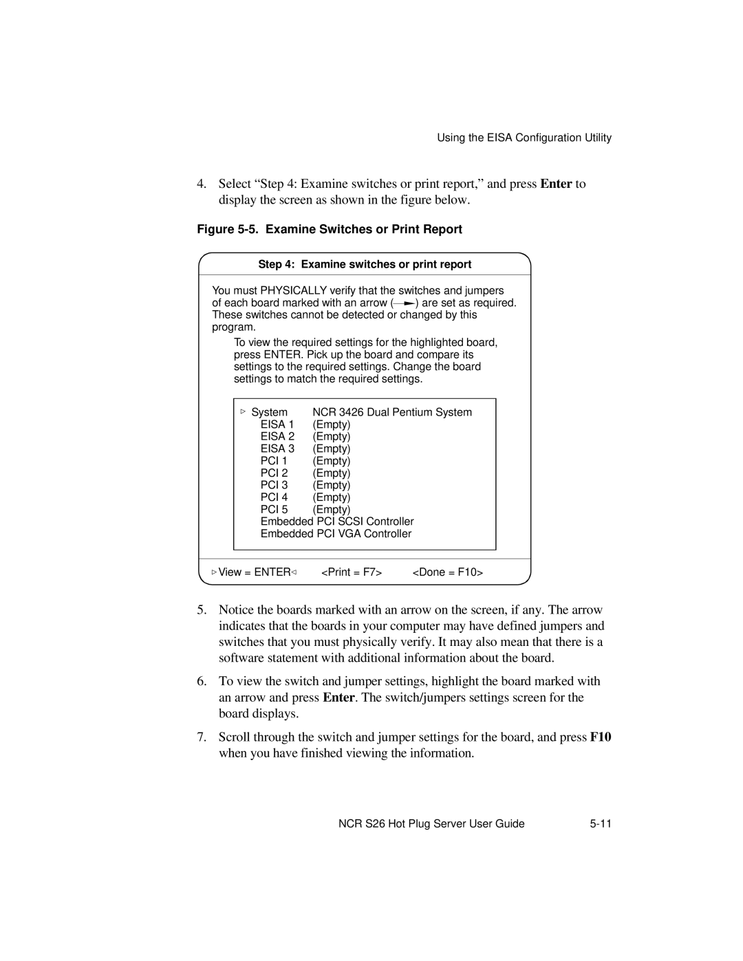
Figure 5-5. Examine Switches or Print Report
Step 4: Examine switches or print report
You must PHYSICALLY verify that the switches and jumpers
of each board marked with an arrow (![]() ) are set as required. These switches cannot be detected or changed by this program.
) are set as required. These switches cannot be detected or changed by this program.
To view the required settings for the highlighted board, press ENTER. Pick up the board and compare its settings to the required settings. Change the board settings to match the required settings.
System | NCR 3426 Dual Pentium System |
EISA 1 | (Empty) |
EISA 2 | (Empty) |
EISA 3 | (Empty) |
PCI 1 | (Empty) |
PCI 2 | (Empty) |
PCI 3 | (Empty) |
PCI 4 | (Empty) |
PCI 5 | (Empty) |
Embedded PCI SCSI Controller
Embedded PCI VGA Controller
View = ENTER | <Print = F7> | <Done = F10> |
5.Notice the boards marked with an arrow on the screen, if any. The arrow indicates that the boards in your computer may have defined jumpers and switches that you must physically verify. It may also mean that there is a software statement with additional information about the board.
6.To view the switch and jumper settings, highlight the board marked with an arrow and press Enter. The switch/jumpers settings screen for the board displays.
7.Scroll through the switch and jumper settings for the board, and press F10 when you have finished viewing the information.
NCR S26 Hot Plug Server User Guide |