Configuring the System Board
∙One shared slot (EISA or PCI)
∙256 KB flash ROM for easy system BIOS upgrade
∙System clock/calendar plus 8 KB extended CMOS RAM with battery backup
∙Onboard
∙
∙Remote Diagnostic Management (RDM) module
∙I/O interfaces for one video slot, two serial ports, one parallel port, peripheral drives, IDE drives, and one PS/2 keyboard and mouse
∙Power connector for
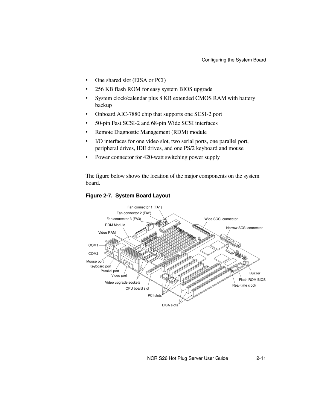
The figure below shows the location of the major components on the system board.
Figure 2-7. System Board Layout
Fan connector 1 (FA1) |
|
Fan connector 2 (FA2) |
|
Fan connector 3 (FA3) | Wide SCSI connector |
RDM Module | Narrow SCSI connector |
| |
Video RAM |
|
COM1
COM2
Mouse port Keyboard port
Parallel port
Buzzer
Video port
Flash ROM BIOS
Video upgrade sockets
CPU board slot
PCI slots
EISA slots
NCR S26 Hot Plug Server User Guide |