SCSI Channel Configurations
Single-Channel Configuration
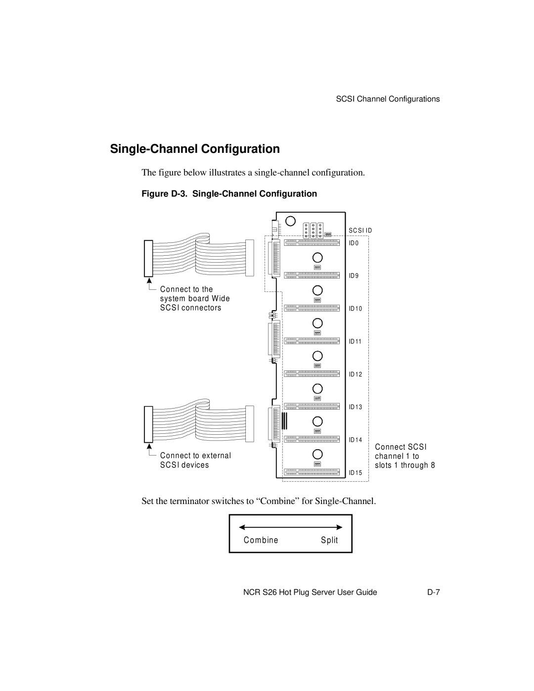
The figure below illustrates a single-channel configuration.
Figure D-3. Single-Channel Configuration
![]() Connect to the
Connect to the
system board Wide SCSI connectors
![]() Connect to external SCSI devices
Connect to external SCSI devices
SC SI ID ID 0 ![]()
ID 9
ID 10
ID 11
ID 12
ID 13
ID 14
ID 15
Connect SCSI channel 1 to slots 1 through 8
Set the terminator switches to “Combine” for
C o m b ine | S plit |
NCR S26 Hot Plug Server User Guide |