Installation
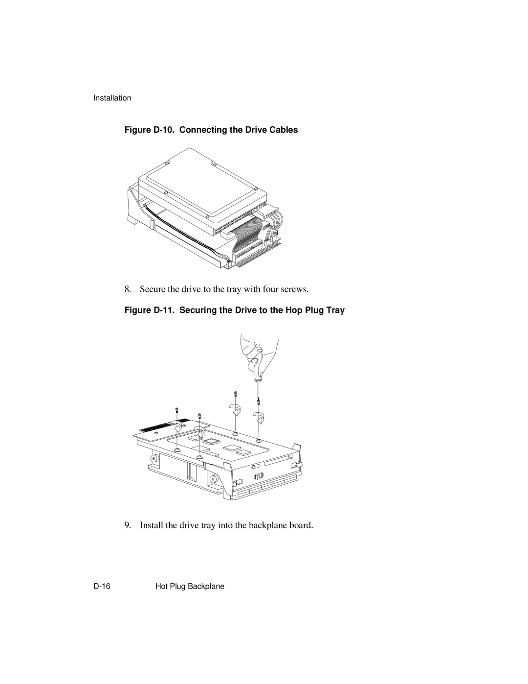
Figure D-10. Connecting the Drive Cables
8. Secure the drive to the tray with four screws.
Figure D-11. Securing the Drive to the Hop Plug Tray
9. Install the drive tray into the backplane board.
Hot Plug Backplane |