Manuals
/
NCR
/
Computer Equipment
/
Server
NCR
S26
manual
Inserting the Drive into the Drive Bay
Models:
S26
1
54
220
220
Download
220 pages
9.55 Kb
51
52
53
54
55
56
57
58
Install
Error codes
Password
Correcting Error Conditions
IDE Hard Disk Standby Timer
Maintenance
Configuring the System Board
Accessing the ECU
Using the Bios Setup Utility
Connector Functions
Page 54
Image 54
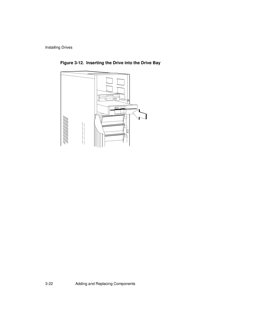
Installing Drives
Figure
3-12.
Inserting the Drive into the Drive Bay
3-22
Adding and Replacing Components
Page 53
Page 55
Page 54
Image 54
Page 53
Page 55
Contents
NCR S26 Hot Plug Server
Page
Contents
Using the Bios Setup Utility
Adding and Replacing Components
Using the System Utilities
IRQ/DMA
Sample Configurations
Watt Power Supply Requirements
Error Messages
Hot Plug Backplane
System Support Log
ViiiContents
About This Book
Who Should Read This Book
Enter
Conventions Used in This Book
Related Publications
+ Y
Installation and Documentation Overview
Chapter
Where to Start
Step What to Do How to Do It Where to Find Information
Documentation and Additional Help
Documentation
Additional Help
Declaration of the Manufacturer or Importer
Safety Compliance
Compliance and Regulatory Statements
Electromagnetic Compatibility EMC
Electromagnetic Compatibility Notice USA
FCC Declaration of Conformity
Product Type Colred
Electromagnetic Compatibility Notices International
Using System Features
ESD Precautions
Identifying System Features
Front View
Identifying System Features
Identifying the Rear Panel Features
Rear Panel Features
Positioning the System
Arranging the System in a Stable Position Bottom View
Allowing for Air Circulation Bottom View
Opening the System
Opening the System
Opening the Cabinet Housing
Configuring the System Board
Features
Major Components
System Board Layout
Jumper Settings
System Board Jumper Locations
Connector Functions
Connector Functions
Jumper Settings
Jumper Setting Function
SW1
Adding and Replacing Components
Adding and Replacing Components
Installing CPU Boards
Installation
Types of CPU Boards
Installing CPU Boards
Upgrading the Memory
Configurations
Memory Configurations
Bank Total Memory
Restrictions
Installing and Removing SIMMs
Simm Sockets
Installing SIMMs
Installing a Simm
Removing SIMMs
Removing a Simm
Reconfiguring the System
Installing a Video Memory Chip
Upgrading the Video Memory
Expanding the PCI System
Installing PCI Devices
Using the Scsi Feature
Installing and Removing Expansion Boards
Identifying Expansion Boards
Installing an Expansion Board
Removing a Bracket
Installing a Board
Removing an Expansion Board
Installing Drives
Removing the Upper Front Panel Cover and Frame
Installing a 3.5-inch Peripheral Drive
Securing the Drive on the Frame
10. Securing the Drive
Installing a 5.25-inch Peripheral Drive
11. Securing the Drive Guides
12. Inserting the Drive into the Drive Bay
Installing a Hot Plug Fixed Disk Drive
Removing a 5.25-inch Peripheral Drive
Installing Drives
Using the Bios Setup Utility
When to Use the Bios Setup Utility
Run Setup Message Repeatedly Received
Before Running Setup
Entering Setup
Bios Utility
Basic System Configuration
Basic System Configuration Menu,
Date and Time
Diskette Drives
Date
Time
IDE Hard Disk Drives
Selecting the Auto Option
Communication Settings
System Memory
Selecting the User Option
On Board IDE
Enhanced IDE Features
Hard Disk Block Mode
Hard Disk Size 504 MB
Auto Configuration Mode
Large Memory Support Mode
Num Lock After Boot
Memory Test
Fast Boot Mode
Advanced System Configuration
Advanced System Configuration, Page One
Internal Cache CPU Cache
ECC/Parity Mode Selection
Shadow RAM
External Cache
Memory at 15 MB 16 MB
Operation of ECC
PCI System Configuration
PCI IRQ Setting
Onboard VGA
VGA Palette Snoop
PCI Slots
Onboard Scsi
Boot Device
Onboard Scsi
Non-PnP ISA Card Configuration
Non-PnP ISA Card Configuration, Page One
Non-PnP ISA Card Configuration, Page Two
Expansion ROM Region
Region
Power Saving Configuration
Power Management Mode
Power Saving Configuration
IDE Hard Disk Standby Timer
System Suspend Timer
System Wake Up Events
System Security
Disk Drive Control
Onboard Communication Ports
System Boot Drive
Drive Control Settings
Diskette Drive
Serial Port 1 Base Address
Serial Port 1 Settings
Serial Port 2 Settings
Serial Port 2 Base Address
Parallel Port Settings
Parallel Port Operation Mode Settings
Setting Function
If You Forget the Password
Setup Password
Setting a Password
Onboard PS/2 Mouse IRQ
Power On Password
Remote Diagnostic Configuration
Load Setup Default Settings
Leaving Setup
Hard Disk Drive Types
Hard Disk Drive Types
Type Cylinders Heads Sectors Per Track
Type Cylinders Heads Sectors Per Track
Type Cylinders Heads Sectors Per Track
Type Cylinders Heads Sectors Per Track
Using the System Utilities
Identifying the System Utilities
Using the AFlash Bios Utility
Executing AFlash
Quick Way to Execute AFlash
Using the Eisa Configuration Utility
Functions
Making Menu Selections
Using the Keyboard
Using the Mouse
Keyboard Function Keys
Accessing the ECU
Getting Help
Main Menu
Setting the Date and Time
Learn About Configuring Your Computer
Configure Computer
Steps in configuring your computer
Maintain System Configuration Diskette
Maintain System Configuration Diskette
Exit from this Utility
Configuring Your Computer Initially
Important Eisa configuration information
Examine Switches or Print Report
Examine switches or print report
Using the Eisa Configuration Utility
Save and Exit
Save and Exit
Adding or Removing Boards
Adding Boards
Add or Remove Boards
Viewing or Editing Configuration Details
Removing a Board
See the next page for continuation of the above screen
Standard VGA Resources
Watt Power Supply Requirements
Appendix a
Table A-1 -Watt Power Supply Input Requirements
Input Requirements
Input Nominal Frequency Variations
Table A-2 -Watt Power Supply Output Requirements
Output Requirements
Output Requirements
Error Messages
Appendix B
Types of Error Messages
Software Error Messages
System Error Messages
Table B-1. Error Messages
Message Action
Mmmmssssooo WXXXX,RYYYY
Correcting Error Conditions
Sample Configurations
Appendix C
Types of Sample Configurations
Sample Standard Configuration
Installing the Hardware
Configuring the System Settings
Basic System Configuration
Advanced System Configuration
Non-PnP ISA Card Configuration
Power Saving Configuration
Remote Diagnostic Configuration
System Security
Configuring the PCI Adapters
Configuring the Scsi Adapters and Drives
Sample Standard Configuration
If the ECU Will Not Boot
Configuring Memory and Other Baseboard Settings
Keyboard Port
Enabled as LPT1 3BCh
Sample RAID Configuration
Install the PCI Ethernet Adapter in PCI slot
Advanced System Configuration
Power Saving Configuration
Sample RAID Configuration On Board PS/2 Mouse IRQ
Configuring the Scsi Adapters and Drives
Press Esc to return to previous menu
Configuring the Memory and Other Baseboard Settings
Enabled as LPT1 3BCh
Configuring the Mylex RAID Array Group
Hot Plug Backplane
Appendix D
Features
Major Components
Hot Plug Backplane
Figure D-1. Hot Plug Backplane Components
Hot Plug Scsi Drive Tray
Figure D-2. Hot Plug Scsi Drive Tray Components
Scsi Channel Configurations
Single-Channel Configuration
Figure D-3. Single-Channel Configuration
Terminator Setting With External Device
Without External Device
Dual-Channel Configuration
Figure D-5. Dual-Channel Configuration
Figure D-6. J3 and J4 Jumper Settings
Setting Hard Disk ID Options
Strapping the Scsi IDs on the Backplane
ID #
Table D-3. Scsi Drive ID Settings
Strapping the Scsi IDs on the Drive
Installation
Using the System Board Scsi Connectors
Figure D-9. Installing the Hot Plug Backplane
Secure the drive to the tray with four screws
Figure D-12. Installing the Hot Plug Drive Tray
Using an Add-on Scsi Controller Board
Installation
Using the Hot Plug Feature
System Support Log
Appendix E
Introduction
System Identification
NCR Hardware Support Services
NCR On-Site Hardware Support Services
NCR Technical Support Web Site
NCR Support Phone Numbers
Before Placing a Hardware Support Call
Placing a Hardware Support Call
Placing a Software Support Call
List of NCR Support Telephone Numbers
NCR Faxback System
United States Support
Other Areas Support
Table E-1. Support Telephone Numbers for Specific Countries
Country Toll-free number Toll number
PRC
Customer Support Agreement
Overview
Support Services
System Numbers
NCR Support Phone Numbers
Priority Plus Next Day
Placing a Hardware Support Call
Placing a Software Support Call
One Log for All Service
Hardware Records
Different Types of Logs
Hardware Records
Hardware Log
Customer
Entry
UUU
UUU
UUU
UUU
UUU
UUU
UUU
Software Records
This page intentionally left blank
Software Product Log
System Product Serial Number
Software Product Log
Software Product Log
Software Product Log
System Software Log
Customer Entry NCR Entry
Problem Symptom Failure#, error#
System Software Log
System Software Log
System Software Log
System Software Log
System Software Log
System Software Log
Adapter Board Locations
Current System Configuration
Hardware Configuration Report
System Equipment List
Adapter Board Locations
PCI Slot PCI Slot 5 Shared Eisa Slot 3 Shared
System Equipment List
System Equipment List
Hardware Configuration
Preventive Maintenance
General Customer Preventive Maintenance Guidelines
Central Processor Unit CPU
Tape Drives
General Customer Preventive Maintenance Procedures
Disk Drives
Plotters
Preventive Maintenance
Preventive Maintenance Timetable Worksheet
Product Jan Feb Mar Apr May Jun Jul Aug Sep Oct Nov Dec
Preventive Maintenance Timetable Worksheet
Preventive Maintenance Reference Sheet
Preventive Maintenance Reference Sheet
Installation Records
Customer Support Agreement
List of NCR Support Telephone Numbers
NCR Faxback System
United States Support
Country Number
Index
IDE
Ventilation
Index Index-4
Top
Page
Image
Contents