SCSI Channel Configurations
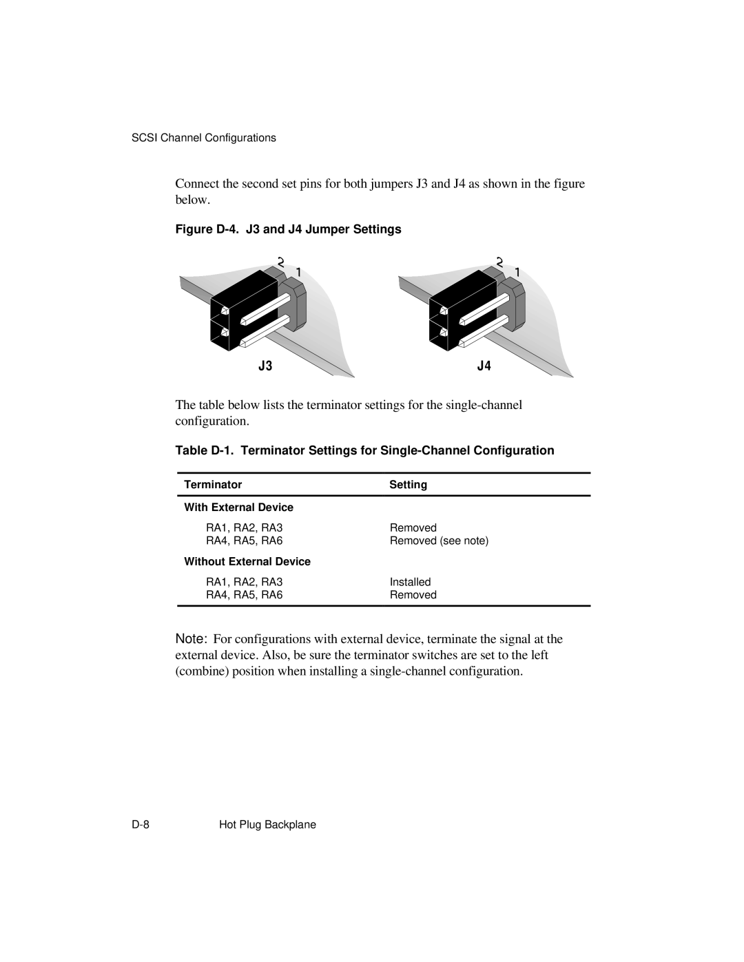
Connect the second set pins for both jumpers J3 and J4 as shown in the figure
below. |
|
Figure |
|
J3 | J4 |
The table below lists the terminator settings for the
Table
Terminator | Setting |
With External Device |
|
RA1, RA2, RA3 | Removed |
RA4, RA5, RA6 | Removed (see note) |
Without External Device |
|
RA1, RA2, RA3 | Installed |
RA4, RA5, RA6 | Removed |
|
|
Note: For configurations with external device, terminate the signal at the external device. Also, be sure the terminator switches are set to the left (combine) position when installing a
Hot Plug Backplane |