2-6 User’s Reference Guide
Netopia R2020 Dual Analog Router Status Lights
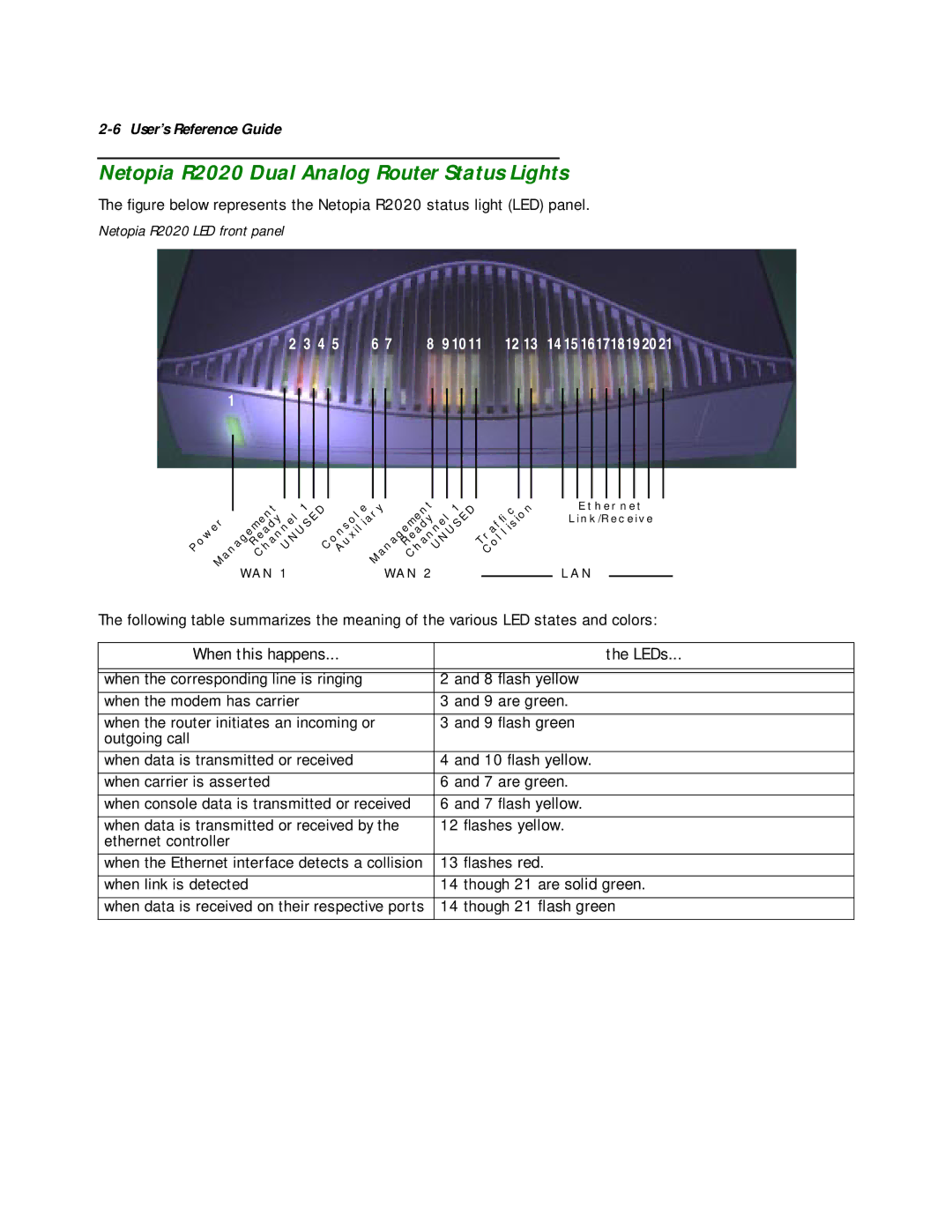
The figure below represents the Netopia R2020 status light (LED) panel.
Netopia R2020 LED front panel
2 | 3 4 5 | 6 7 | 8 | 9 10 11 | 12 13 | 14 15 16171819 20 21 |
1
P |
|
| C |
| 1 | A |
|
| ANAGEMENTHANNEL | 1 | ||||
|
| ANAGEMENT |
| UXILIARY | C |
| ||||||||
|
|
|
|
|
| |||||||||
| OWER | R |
|
|
|
| R |
|
|
| ||||
|
|
|
|
| HANNELUNUSEDC | ONSOLE |
|
|
| EADY | UNUSED | |||
|
|
|
| EADY |
|
|
|
|
|
|
|
| ||
| M |
| WAN 1 |
|
|
| M |
| WAN 2 |
| ||||
|
|
|
|
|
|
|
|
| ||||||
T |
| OLLISION | |
| RAFfi | C | |
|
| ||
| C |
|
|
|
|
|
|
ETHERNET
LINK/RECEIVE
LAN
The following table summarizes the meaning of the various LED states and colors:
When this happens... | the LEDs... |
|
|
|
|
when the corresponding line is ringing | 2 and 8 flash yellow |
when the modem has carrier | 3 and 9 are green. |
|
|
when the router initiates an incoming or | 3 and 9 flash green |
outgoing call |
|
|
|
when data is transmitted or received | 4 and 10 flash yellow. |
|
|
when carrier is asserted | 6 and 7 are green. |
|
|
when console data is transmitted or received | 6 and 7 flash yellow. |
|
|
when data is transmitted or received by the | 12 flashes yellow. |
ethernet controller |
|
|
|
when the Ethernet interface detects a collision | 13 flashes red. |
|
|
when link is detected | 14 though 21 are solid green. |
|
|
when data is received on their respective ports | 14 though 21 flash green |
|
|