Channel Service Unit Includes Terminal User Interface
Trademarks
Warranty, Sales, and Service Information
Operators Guide 3160-A2-GB22-10
Copyright E 1996 Paradyne Corporation. All rights reserved
Important Safety Instructions
CC DGD D C D CC
Government Requirements and Equipment Return
United States
316x DSU/CSU Facility Interface Codes Description
Canada
Government Requirements
Table of Contents
Glossary Index
LCD
List of Figures
Slide Latch Adapter Cable Feature Number 3100-F1-560
List of Tables
Models 3160/3614 DSU/CSUs Rear Panel Connectors
Acculink 316x DSU/CSU
Objectives and Reader Assumptions
Preface
Related Documents
Reference Documents
Overview
Introduction
Alarm Interface
Features
Integral Modem
User Interface
Front Panel Emulation
Front Panel Access Control Feature
Front Panel Pass-Through
Async Terminal Interface Support
Standalone Model 3160/3164 DSU/CSUs
Acculink 316x DSU/CSU Physical Description
3160/3164 DSU/CSU Front Panel
3160/3164 DSU/CSU Rear Panel
LCD
DSU/CSU Front Panel
DSU/CSU Rear Panel
Models 3160/3164 DSU/CSUs Rear Panel Connectors
Connector Name
Function
Carrier-Mounted Model 3161 DSU/CSU
Model 3161 Front Panel Functions
Model 3161 DSU/CSU Rear Panel
Auxiliary Backplane
Planning
Installation
Network
Fractional T1
Serial Connection to Snmp
Quick Start Procedure
Box Contents
Installing the +24 Vdc Power Supply
Optional Power Selection
±48 Vdc Single Source Power Supply Pinouts
Installing the Single ±48 Vdc Power Supply
±48 Vdc Redundant Source Power Supply Pinouts
Installing the Redundant ±48 Vdc Power Supply
DSU ESF
Power-Up Self-Test
DSU/CSU Identity
Selecting a Model
Status DevHS STest Perf
Status TStat LED ID
Identity Ser=xxxxxxx
Control Reset CID Password
Identity Mod=xxxx-xx-xxx
Identity Cust ID=xxxxxxxx
Setting/Changing a Password
Establishing Access Security on a Port
Passwd Up Down Save
Control Reset CID Passwd
3160/3164 DSU/CSU Cabling
13 /3164 DSU/CSU Cabling Configurations
Installing Front Panel Emulation Software
Factory Default Configuration Options
Enabling/Disabling the Front Panel
3160/3164 DSU/CSU User Interface Access Security
Security Lvl1 Lvl2
Changing User Interface Access Security
LCD
Operation
Acculink 316x DSU/CSU
Operating the Front Panel
Model 3161 DSU/CSU Faceplate
Other Displays
Device Health and Status Messages
Context-Sensitive Menu
Keypad
LEDs
LEDs
Name Color Meaning
System LEDs
SIG
Network Interface LEDs
PDV
DSX-1 Drop/Insert Port LEDs
DTR
Data Port LEDs
DTR TXD
Displaying LED Conditions on the Front Panel
LED Dsply DTE
Selecting the DSX-1 or a Port for LED Display
DTE
Prt1 Prt2
LED Display Selection Screen
Front Panel Emulation on a PC
Front Panel Emulation Screen Icons Name Meaning
Test Jacks
12 DSU/CSU Test Jacks
Configuration Option Areas
Configuring the DSU/CSU
Configuration Options
Test Jack Functions
14. Configuration Branch for the Front Panel
Configuration Procedures
15. Configuration Branch for the Async Terminal
Displaying/Editing Configuration Options
16. Load From Screen
NET Framing ESF Next D4 ESF
Save Edit to Activ Cust
Saving Edit Changes
Selecting/Copying to a Specific Port
Selecting a Specific Port
Port Select Copy Prt1 Prt2
Prt2 Value Options
Prt1 Value Options
Prt3 Value Options
Prt4 Value Options
To Copy to One or All Ports
Copy From Prt1 Prt2 Prt3
Copy To All Prt1 Prt2
Selecting the Port
Configuring the 3160/3164 DSU/CSU for Snmp Management
Modem Use Next Snmp Ascii
Com Use Next Snmp Ascii
Setting the IP Address
Snmp Config Gen Trap
Edit User Alarm
Snmp
System Name Next Edit Clear
Selecting the Link Layer Protocol
000.000.000.000 Up Down Save
010.155.111.222 Up Down Save
Modem Link Next PPP Slip
Specifying the Community Names and Access Types
Public Up Down Save
CommunityName1 Next Edit Clear
Snmp Traps
Access Next Read R/W
Newname Up Down Save
Enterprise-Specific Trap Definitions Trap Value Event
Num Trap Mgrs1 Next
Selecting the Number of Trap Managers
23. Trap Options Screen
Configuring an IP Address for Snmp Trap Manager
Trap n IP Adr Next Edit Clear
Configuring DS0 Channels
24. Example Channel Allocation
25. Example Interface Tables
Network T1 Interface Network Channel Allocation
26. DS0 Channels Containing RBS Information Worksheet
DTE Chan Assign Voice Config N1 ± RBS or Data
NET, DTE
Port Chan Options Value Conf
Port Chan Options Value Conf
Channel Config Dsply Clear DTE
Display Channel Symbols Meaning
Displaying DS0 Channel Assignments
Edit Port NET Chan
Display Chan
NET DTE
Prt1
Allocating Data Ports
NET
Block Channel Assignment Method Example
Port Rate384 Next 64
Acami Channel Assignment Method Example
Start AtClear Next Clear N1
Assign ByACAMI Next Block Acami
Assign ByChan Block Acami Chan
Individual Channel Assignment Method Example
Assign ByChan Next Block Acami
Next Prt1 Prt2
DTE Channels Assign Voice
RBS
30. DTE Assignment Screen
Clear Channel
Clearing DS0 Channel Allocation
Timing
32. Common Clocking Configurations
Edit NET Chan Gen
Configuring for Network Timing Example
GenYellowEnab Next Enab Disab
Clock SrcNET Next NET DTE
Configuring for External Timing Example
Clock SrcNET Prt1 Int Ext
Clock Rate1544 Next 2048
Selecting the Shared Communication Port
101
Self±TestEnab Next Enab Disab
Checking the Status
Device Health and Status
MasterComDisab Next Enab Disab
Health and Status Messages
Message
Description
Self-Test Health
Displaying Device Health and Status
Device H/S OOF at DTE
Auto Dev H/S OOF at DTE
Self-Test Health Messages
Displaying Self-Test Results
Message Description
STest Health Passed
Performance Report
CurTimer
Event=xx,xxx
VldIntvl=xx
StEvnt
35. Carrier Telco and User Register Organization
Displaying User Performance Registers
36. Telco Performance Report Screen
Clearing User Performance Registers
LED
Controlling the DSU/CSU
Acquiring the Active Physical Interface
Acquiring/Releasing the Active Physical Interface
Releasing the Active Physical Interface
DSU Fmt
Using the Integral Modem
Initiating a Call for Front Panel Pass-Through Operation
Ft. Panel Released
Call Setup Pass Dial ChDir
Pass n Up Down Dial
Dial n Up Down Dial
Passwd Up Down Done
Entering a Password to Gain Access
Disconnecting Using the Disconnect Command
Disconnecting the Modem Connection
Disconnecting Using Front Panel Keys
Call Setup Disc ChDir
Xxxxxxxxxxxxxxxxx Next Prev Edit
Entering Numbers in the Phone Directories
Valid Phone Number Characters Meaning Restrictions
Xxxxxxxxxxxxxxxxx Up Down Save
Alarm Cut-Off Command Complete
Deactivating the Alarm Relay
Starting Front Panel Emulation
Control ACO Rel LED
Setting Interface Options
Using the Async Terminal Feature
Activating Interface Option Changes
Entering a Password
Initiating an Async Terminal Session
Async Terminal Menus and Screens
Edit and Display Screens
Menu Selection Screens
Function Representations for Edit Screens Function Key Usage
Hard-Key Representations for Edit Screens Usage
Terminating a Session
Troubleshooting
Maintenance
Snmp Traps
Alarms
Snmp Trap per Interface
Interface Snmp Trap Meaning
Test Branch
Test Commands
Sending a Line Loopback Up or Down
Remote Loopback Tests
Test Rlpbk Lpbk Ptrns
Rem Loopback
Sending a V.54/ANSI FT1 Activation/Deactivation
Local Loopback Tests
Rem Loop Type Prt1 Prt2 Prt3
Starting a Line Loopback
Valid Loopback Combinations
Loopback Abort LLB PLB
Starting a DTE Loopback
Starting a Payload Loopback
Starting a Repeater Loopback
Loopback
LLB PLB DLB
PLB DLB RLB
Starting a Data Channel Loopback
DLB RLB Dclb
Loopback Dclb Prt1 Prt2 Prt3
Starting a Data Terminal Loopback
RLB Dclb Dtlb
Loopback Dtlb Prt1 Prt2 Prt3
Aborting Loopbacks
DTE-initiated Loopbacks
Loopback Abort All
LLB PLB
Sending Test Patterns
Test Patterns
8 Network Port
Monitoring Test Patterns
Patterns Mon Qrss
Monitor Name NET Prt1 Prt2
Lamp Test
Aborting Test Patterns
Starting a Lamp Test
Patterns Abort All Send Mon
Test Lpbk Ptrns Lamp
Aborting a Lamp Test
Lamp Test Abort Start
0123456789 = ?
Test Status Messages
Displaying DSU/CSU Test Status
Resetting the DSU/CSU
Downloading Software
Status STest Perf TStat
Device Reset Yes No
Control ClrUsr Reset
Front Panel Menu a
3160-A2-GB22-10
Front Panel Menu
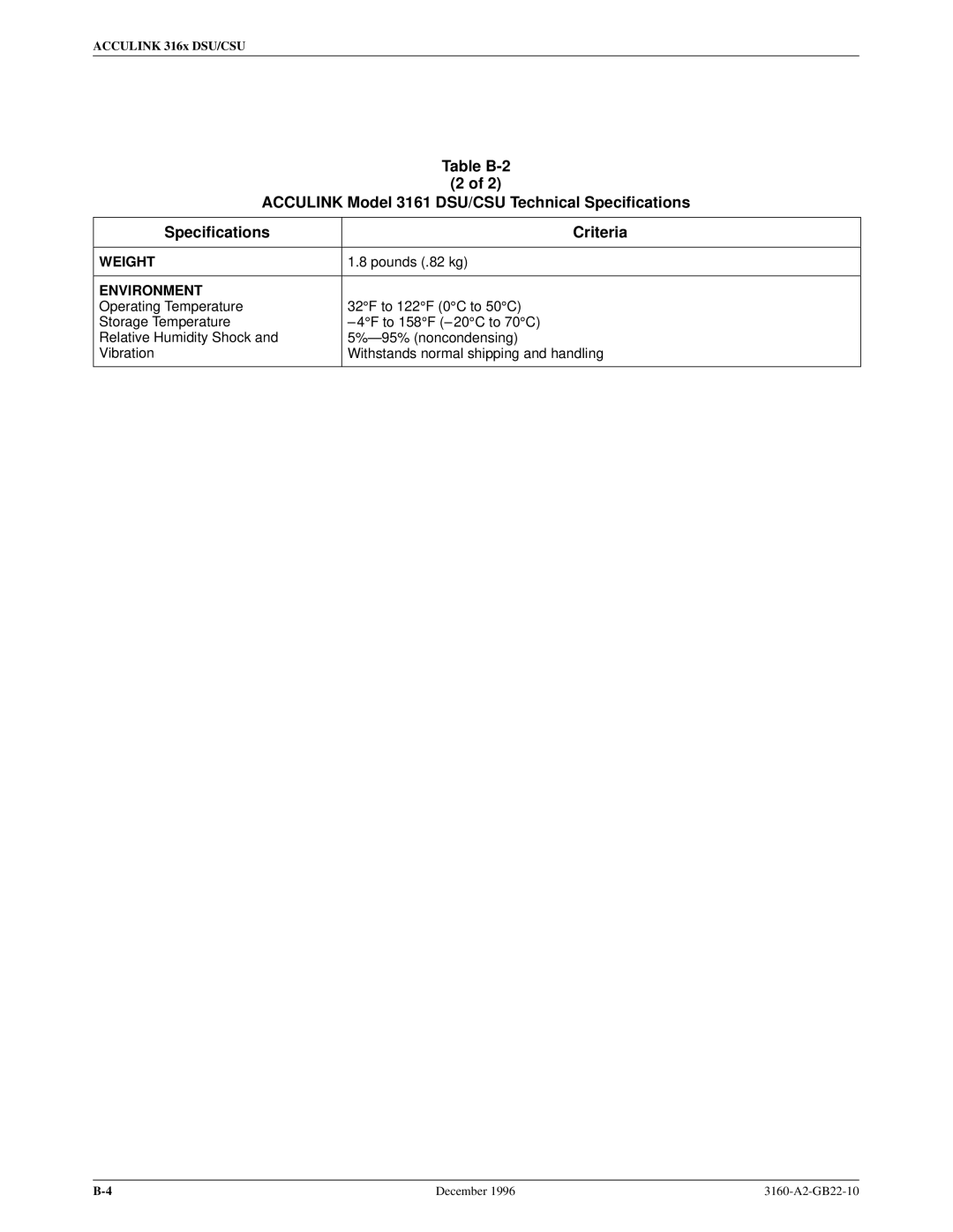
Power Requirements
Technical Specifications B
Clocking Sources
Power Consumption Dissipation
Pounds .82 kg
Functional Grouping
Configuration Options C
DTE Interface Configuration Options
Table C-1 DTE Interface Configuration Options
Context-Sensitive Menu
Send Ones Enab Next Enab Disab Prev
Extrn DLB Disab Next Enab Disab Prev
Port Configuration Options
Port Configuration Options
Table C-2
Port Type E530 Factory Next E530 V.35 RS449 Prev
Table C-2 Port Configuration Options
All Ones Both Next Disab DTR RTS Both Prev
Rcv Yellow Halt Next None Halt Prev
Tx Clock Int Next Int Ext Prev
Invert TxC Disab Next Enab Disab Prev
Invert Data Disab Next Enab Disab Prev
Table C-3 Network Interface Configuration Options
Network Interface Configuration Options
Bit Stuff Next 62411 Part68 Disab Prev
NET PLB Enab Next Enab Disab Prev
Table C-4 DTE Channel Configuration Options
Channel Configuration Options
Table C-5 Data Port Channel Configuration Options
N10 N11 N12 N24 Next Prev D10 D11 D12 D24
Start At Clear Next N10 N11 N24 Prev D10 D11 D24
Table C-6 General Configuration Options
General Configuration Options
Gen Yellow Enab Next Enab Disab Prev
Clock Src NET Next NET DTE Prt1 Int Ext Prev
Table C-7 User Interface Configuration Options
User Interface Configuration Options
Com Use Ascii Next Snmp Ascii Term Prev
MasterComDisab Next Enab Disab Prev
Com Type Async Next Async Sync Prev
Com Clk Int Next Int Ext Prev
Char Length Next 7 8 Prev
Com Rate Next 1.2 2.4 4.8 9.6 14.4 19.2 Prev
CParity None Next None Even Odd Prev
CStop Bits Next 1 1.5 2 Prev
Modem Rate Next 1.2 2.4 Prev
Modem Type Async Next Async Sync Prev
MChar Len Next 7 8 Prev
MParity None Next None Even Odd Prev
Table C-8 Alarm Configuration Options
Alarm Configuration Options
Alrm Msg Disab Next Disab Modem Com Both Prev
Snmp Trap Disab Next Enab Disab Prev
DialOut Disab Next Enab Disab Prev
Dial Delay Next 1 2 3 4 5 6 7 8 9 10 Prev
Call Retry Disab Next Enab Disab Prev
Next None 1 2 3 4 5 Prev
AlrmRelay Disab Next Enab Disab Prev
Err Rate 10E-4 Next 10E-4 10E-5 10E-6 10E-7 10E-8 10E-9 Prev
Table C-9 General Snmp Configuration Options
Snmp Configuration Options
Com IP Adr Clear Next Edit Clear Prev
Access 2 Read Next Read R/W Prev
Com Link PPP Next PPP Slip Prev
Modem IP Adr Clear Next Edit Clear Prev
Num Trap Mgrs Next 1 2 3 4 5 6 Prev
Table C-10 Snmp Trap Configuration Options
Trap n IP Adr Clear Next Edit Clear Prev
Gen Trap Both Next Disab Warm Auth Both Prev
Trap I/F All Next NET DTE T1s Ports All Prev
Link Trap Both Next Disab Up Down Both Prev
T1 Network Connector Interface
Pin Assignments D
Cables
Receiver Ring Receiver Tip Transmitter Ring Transmitter Tip
RJ48C DA15P
DSX-1 Port DTE Interface
Integral Modem Service Port Interface
AUX Port Interface
COM Port Interface
Figure D-5. COM Port-to-PC Cable Feature Number 3100-F1-550
Acculink 316x DSU/CSU
EIA-530A DB25 Port Interface Connector
Table D-7 EIA-530A Port Interface Connector Signal Circuit
Direction Pin Mnemonic Number
Table D-8 RS449 Port Interface Connector Signal Circuit
RS449 Port Interface Connector
Pin Assignments
Port Interface Connector
Table D-9 Port Interface Connectors Signal
Direction Pin Number
Pin Assignments
Power Cable
Power Input Connector
Table D-10 DC Power Connector Signal Pin Number
External Clock Connector
Slide Latch Adapter
Figure D-11. The connector information is in Table D-12
Snmp MIB Objects E
System Group Supported
Management Information Base MIB II RFC
System Group, MIB
System Group ± ªsysServicesº Object system
System Group ± ªsysDescrº Object system
System Group ± ªsysObjectIDº Object system
Interface Group ± ªifDescrº Object ifEntry
Interface Group, MIB
Interface Group ± ªifTypeº Object ifEntry
Interface Group ± ªifMtuº Object ifEntry
DTE
Interface Group ± ªifAdminStatusº Object ifEntry
Icmp Group, MIB
IP Group ± ªipNetToMediaTableº Object ip
UDP Group, MIB
IP Group, MIB
DS1/E1 MIB RFC
Near End Group ± ªdsx1SendCodeº Object dsx1ConfigEntry
Near End Group ± ªdsx1LineStatusº Object dsx1ConfigEntry
Near End Group ± ªdsx1SignalModeº Object dsx1ConfigEntry
Near End Group ± ªdsx1Fdlº Object dsx1ConfigEntry
Near End Group ± The DS1 Total Table Objects dsx1TotalEntry
RS-232-like MIB RFC
Far End Group, DS1/E1 MIB
DS1 Fractional Group, DS1/E1 MIB
General Port Table, RS-232-like MIB
Number of Ports ± ªrs232Numberº Object rs232
General Port Table ± ªrs232PortIndexº Object rs232PortEntry
General Port Table ± ªrs232PortTypeº Object rs232PortEntry
Input Signal Table ± ªrs232InSigNameº rs232InSigEntry
Input Signal Table, RS-232-like MIB
Input Signal Table ± ªrs232InSigStateº rs232InSigEntry
Input Signal Table ± ªrs232InSigChangesº rs232InSigEntry
Output Signal Table ± ªrs232OutSigStateº rs232OutSigEntry
Output Signal Table ± ªrs232OutSigNameº rs232OutSigEntry
Output Signal Table ± ªrs232OutSigChangesº rs232OutSigEntry
Generic-Interface MIB Extensions RFC
Acculink 316x DSU/CSU
Troubleshooting Table F
Table F-1 Troubleshooting Symptom Possible Cause Solutions
Yellow at Net
Yellow at DTE
AIS at Net
AIS at DTE
Configuration Worksheets G
Net Value Options
DTE
Configuration Worksheets
Network T1 Interface Network Channel Allocation
D10 D11 D12 D13 D14 D15 D16 D17 D18 D19 D20 D21 D22 D23 D25
Acami
Port Chan Options Value Conf
General Options Value
Alarm Value Options
User Options Value
Snmp Gen Value Options
Equipment List H
Equipment Feature Number
PEC Code
Cable numbers for DSU/CSU are located
AIS
Glossary
EER
Index
DTE
Index
Index-4