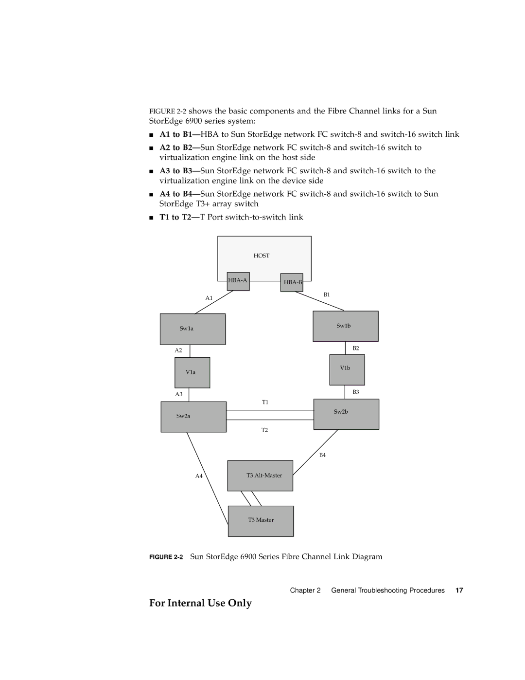
FIGURE 2-2 shows the basic components and the Fibre Channel links for a Sun StorEdge 6900 series system:
■A1 to B1—HBA to Sun StorEdge network FC switch-8 and switch-16 switch link
■A2 to B2—Sun StorEdge network FC switch-8 and switch-16 switch to virtualization engine link on the host side
■A3 to B3—Sun StorEdge network FC switch-8 and switch-16 switch to the virtualization engine link on the device side
■A4 to B4—Sun StorEdge network FC switch-8 and switch-16 switch to Sun StorEdge T3+ array switch
■T1 to T2—T Port switch-to-switch link
A1
Sw1a
A2
V1a
A3
HOST
T1
B1
Sw1b
B2
V1b
B3
Sw2b
Sw2a
T2
B4
A4
T3
T3 Master
FIGURE 2-2 Sun StorEdge 6900 Series Fibre Channel Link Diagram
Chapter 2 General Troubleshooting Procedures 17
For Internal Use Only