6F3B0253
6. Programming Information
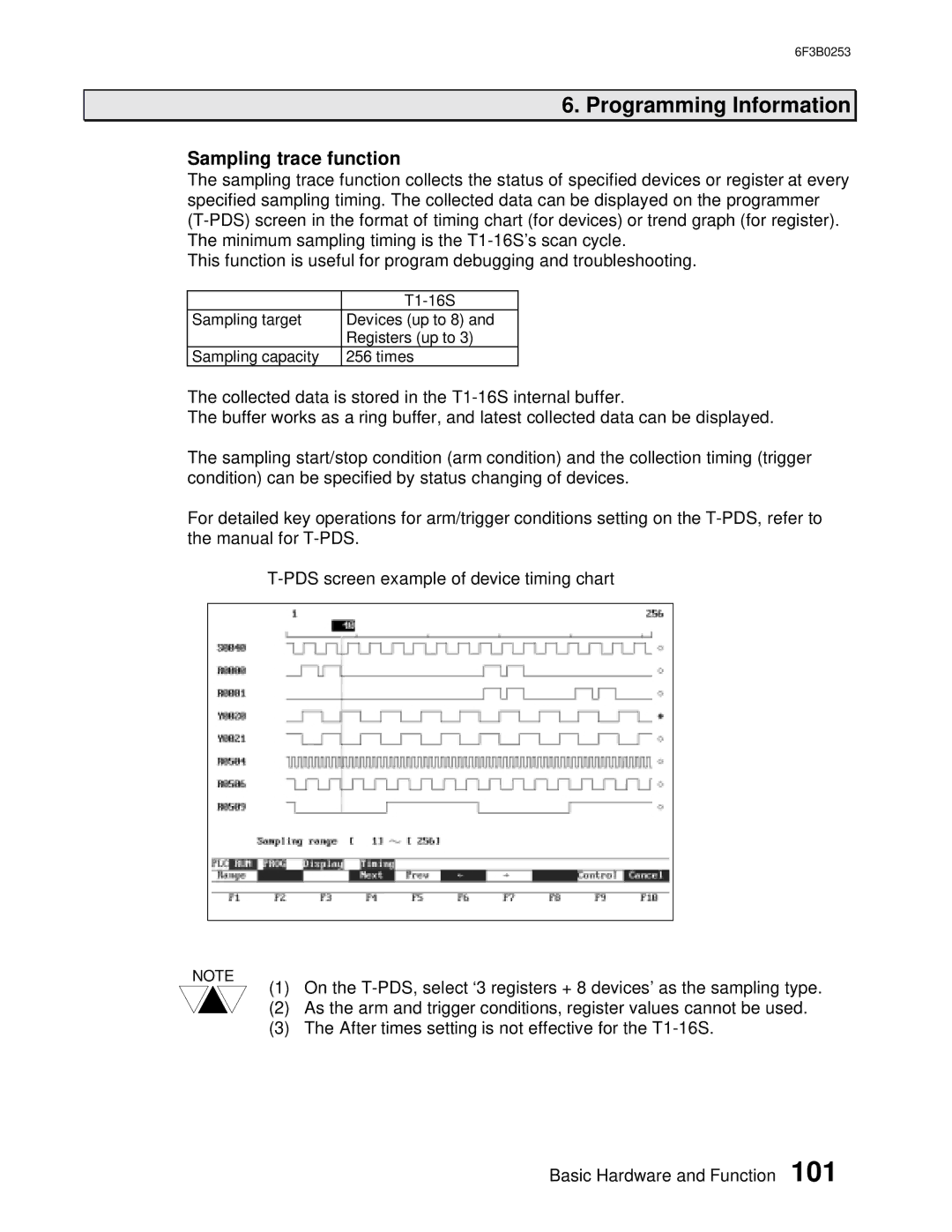
Sampling trace function
The sampling trace function collects the status of specified devices or register at every specified sampling timing. The collected data can be displayed on the programmer
This function is useful for program debugging and troubleshooting.
| |
Sampling target | Devices (up to 8) and |
| Registers (up to 3) |
Sampling capacity | 256 times |
The collected data is stored in the
The buffer works as a ring buffer, and latest collected data can be displayed.
The sampling start/stop condition (arm condition) and the collection timing (trigger condition) can be specified by status changing of devices.
For detailed key operations for arm/trigger conditions setting on the
NOTE | On the |
(1) | |
(2) | As the arm and trigger conditions, register values cannot be used. |
(3) | The After times setting is not effective for the |
Basic Hardware and Function 101