6F3B0253
4. Installation and Wiring
4.2 Installing the unit
1. Improper installation directions or insufficient installation can cause
! CAUTION fire or the units to drop. Install the
2.Turn off power before installing or removing any units, modules, racks or terminal blocks. Failure to do so can cause electrical shock or damage to the
3.Entering wire scraps or other foreign debris into to the
NOTE The ![]() for mounting on a 35mm DIN rail.
for mounting on a 35mm DIN rail.
Installation precautions:
•Because the
•Do not install the unit directly above equipment that generates a large amount of heat, such as a heater, transformer, or
•Do not install the unit within 200mm of
•Allow at least 70mm on all sides of the unit for ventilation.
•For safely during maintenance and operation, install the unit as far as possible from
•If
•Be sure to install the unit vertically with keeping the power terminals downside. Do not install the unit horizontally or
•Use M4 size screws to mount the
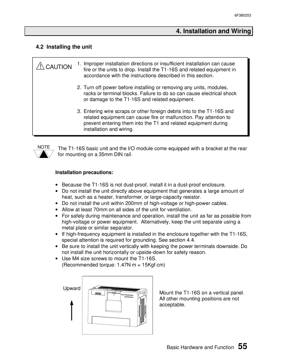
Upward |
Mount the
Basic Hardware and Function 55