6F3B0253
7. Instructions
< Broadcast mode (Mode 4) >
When the instruction input comes ON with the operand B+1 is 4, the Broadcast mode (mode 4) is selected. In this mode, the
This mode is useful to send Run/Stop command to all the Inverter at the same time.
Repeat
Sends the specified command with command data to all Inverters (broadcast)
Checks the acknowledge from #0 Inverter
The Inverter number specified by the operand B is ignored.
The scan execution status and the Inverter communication status are stored in the operand B+2 to B+7. (only #0 Inverter responds)
The command code and the command data setting registers are indirectly specified by the operand A and A+1.
When the instruction input is reset to OFF, the operation is stopped after receiving the response from the Inverter.
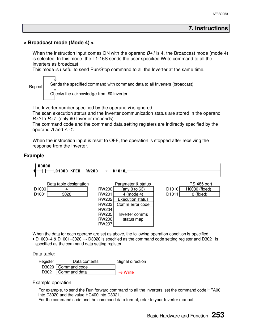
Example
D1000
D1001
Data table designation
4RW200
3020RW201 RW202 RW203 RW204 RW205 RW206 RW207
Parameter & status
(any 0 to 63)
4 (mode 4)
Execution status
Comm error code
Inverter comms
status map
D1010
D1011
H0030 (fixed)
0 (fixed)
When the data for each operand are set as above, the following operation condition is specified.
•D1000=4 & D1001=3020 ⇒ D3020 is specified as the command code setting register and D3021 is specified as the command data setting register.
Data table:
Register
D3020
D3021
Data contents
Command code
Command data
Signal direction
→Write
Example operation:
For example, to send the Run forward command to all the Inverters, set the command code HFA00 into D3020 and the value HC400 into D3021.
For the command code and the command data format, refer to your Inverter manual.
Basic Hardware and Function 253