6F3B0253
7. Instructions
CPU register ↔ built-in EEPROM
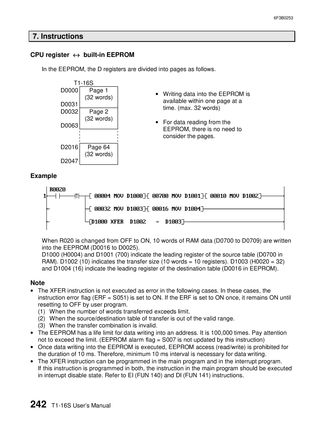
In the EEPROM, the D registers are divided into pages as follows.
D0000 Page 1
(32 words)
D0031 |
|
D0032 | Page 2 |
| (32 words) |
D0063 |
|
|
|
D2016 | Page 64 |
| (32 words) |
D2047 |
|
•Writing data into the EEPROM is available within one page at a time. (max. 32 words)
•For data reading from the EEPROM, there is no need to consider the pages.
Example
When R020 is changed from OFF to ON, 10 words of RAM data (D0700 to D0709) are written into the EEPROM (D0016 to D0025).
D1000 (H0004) and D1001 (700) indicate the leading register of the source table (D0700 in RAM). D1002 (10) indicates the transfer size (10 words = 10 registers). D1003 (H0020 = 32) and D1004 (16) indicate the leading register of the destination table (D0016 in EEPROM).
Note
•The XFER instruction is not executed as error in the following cases. In these cases, the instruction error flag (ERF = S051) is set to ON. If the ERF is set to ON once, it remains ON until resetting to OFF by user program.
(1)When the number of words transferred exceeds limit.
(2)When the source/destination table of transfer is out of the valid range.
(3)When the transfer combination is invalid.
•The EEPROM has a life limit for data writing into an address. It is 100,000 times. Pay attention not to exceed the limit. (EEPROM alarm flag = S007 is not updated by this instruction)
•Once data writing into the EEPROM is executed, EEPROM access (read/write) is prohibited for the duration of 10 ms. Therefore, minimum 10 ms interval is necessary for data writing.
•The XFER instruction can be programmed in the main program and in the interrupt program.
If this instruction is programmed in both, the instruction in the main program should be executed in interrupt disable state. Refer to EI (FUN 140) and DI (FUN 141) instructions.
242