6F3B0253
8. Special I/O Functions
8.1 Special I/O function overview
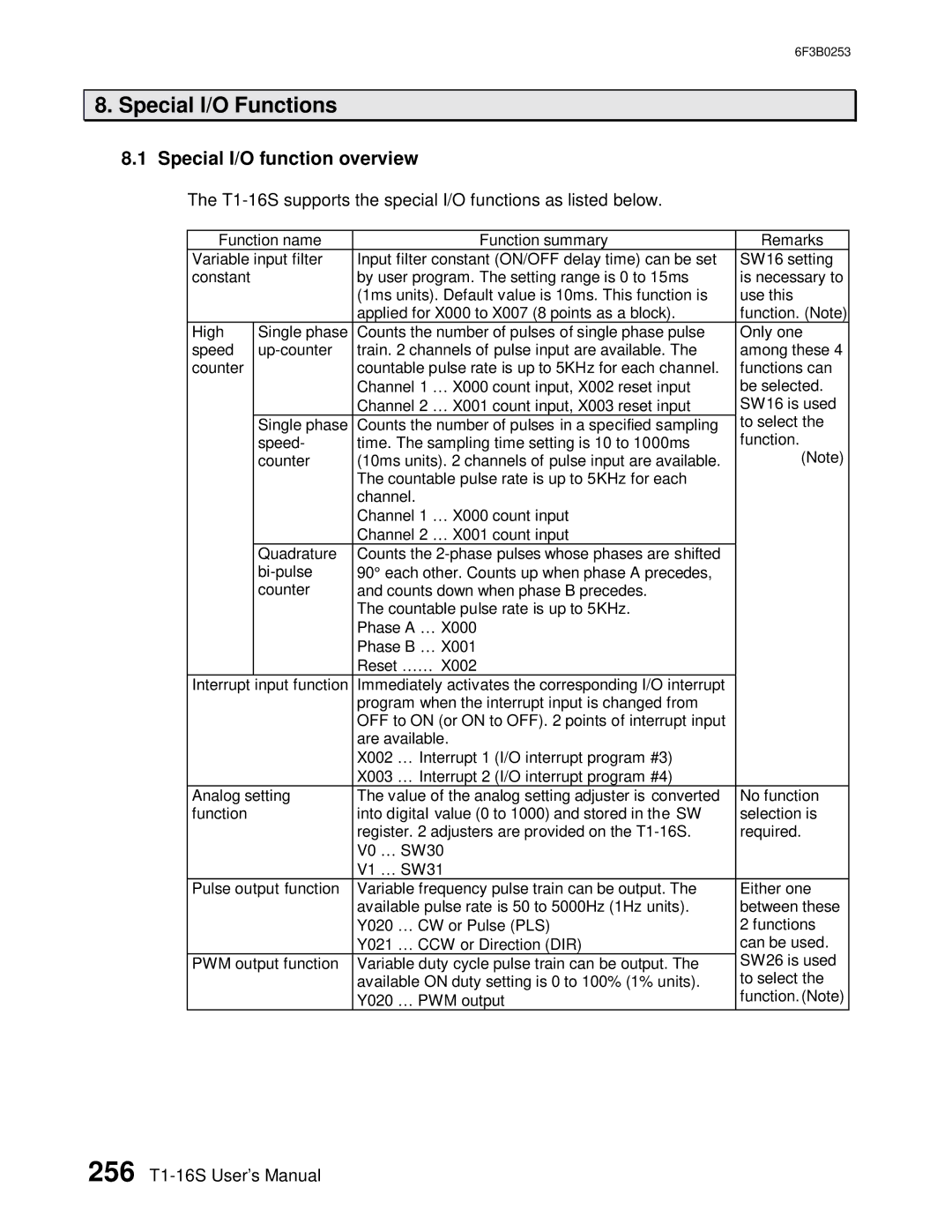
The T1-16S supports the special I/O functions as listed below.
Function name |
|
|
| Function summary | Remarks | |
Variable input filter | Input filter constant (ON/OFF delay time) can be set | SW16 setting | ||||
constant |
| by user program. The setting range is 0 to 15ms | is necessary to | |||
|
| (1ms units). Default value is 10ms. This function is | use this | |||
|
| applied for X000 to X007 (8 points as a block). | function. (Note) | |||
High | Single phase | Counts the number of pulses of single phase pulse | Only one | |||
speed | train. 2 channels of pulse input are available. The | among these 4 | ||||
counter |
| countable pulse rate is up to 5KHz for each channel. | functions can | |||
|
| Channel 1 … X000 count input, X002 reset input | be selected. | |||
|
| Channel 2 … X001 count input, X003 reset input | SW16 is used | |||
| Single phase | Counts the number of pulses in a specified sampling | to select the | |||
| speed- | time. The sampling time setting is 10 to 1000ms | function. | |||
| counter | (10ms units). 2 channels of pulse input are available. | (Note) | |||
|
| The countable pulse rate is up to 5KHz for each |
| |||
|
| channel. |
|
|
| |
|
| Channel 1 … X000 count input |
| |||
|
| Channel 2 … X001 count input |
| |||
| Quadrature | Counts the |
| |||
| 90° | each other. Counts up when phase A precedes, |
| |||
| counter | and counts down when phase B precedes. |
| |||
|
| The countable pulse rate is up to 5KHz. |
| |||
|
| Phase A … | X000 |
| ||
|
| Phase B … | X001 |
| ||
|
| Reset …… |
| X002 |
| |
Interrupt input function | Immediately activates the corresponding I/O interrupt |
| ||||
|
| program when the interrupt input is changed from |
| |||
|
| OFF to ON (or ON to OFF). 2 points of interrupt input |
| |||
|
| are available. |
| |||
|
| X002 … Interrupt 1 (I/O interrupt program #3) |
| |||
|
| X003 … Interrupt 2 (I/O interrupt program #4) |
| |||
Analog setting | The value of the analog setting adjuster is converted | No function | ||||
function |
| into digital value (0 to 1000) and stored in the SW | selection is | |||
|
| register. 2 adjusters are provided on the | required. | |||
|
| V0 … | SW30 |
| ||
|
| V1 … | SW31 |
| ||
Pulse output function | Variable frequency pulse train can be output. The | Either one | ||||
|
| available pulse rate is 50 to 5000Hz (1Hz units). | between these | |||
|
| Y020 … CW or Pulse (PLS) | 2 functions | |||
|
| Y021 … | CCW or Direction (DIR) | can be used. | ||
PWM output function | Variable duty cycle pulse train can be output. The | SW26 is used | ||||
|
| available ON duty setting is 0 to 100% (1% units). | to select the | |||
|
| Y020 … | PWM output | function. (Note) | ||
256