6F3B0253
7. Instructions
CNT
Counter
Expression
Count input
C CNT Q
Output
Enable input
E A B
Function
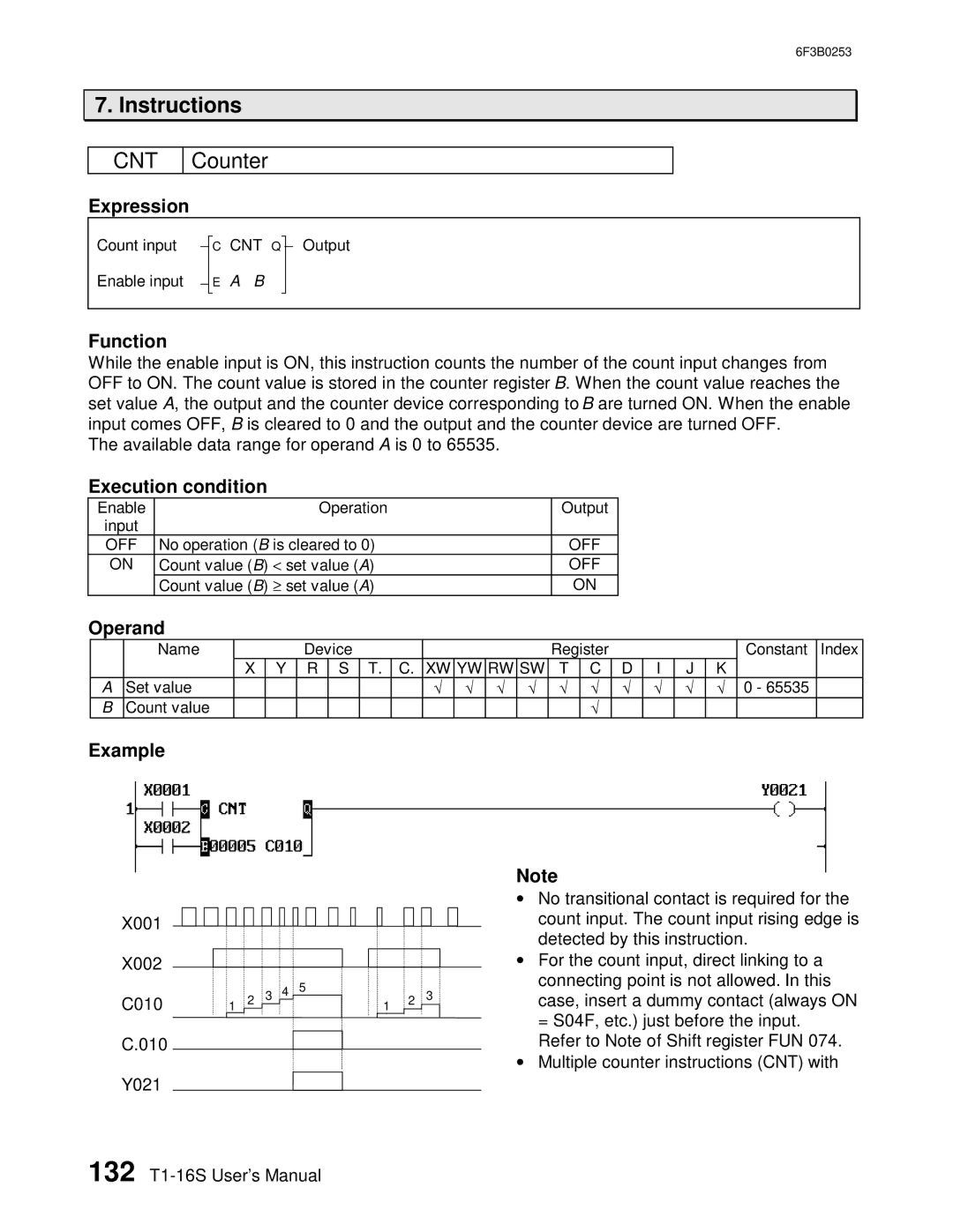
While the enable input is ON, this instruction counts the number of the count input changes from OFF to ON. The count value is stored in the counter register B. When the count value reaches the set value A, the output and the counter device corresponding to B are turned ON. When the enable input comes OFF, B is cleared to 0 and the output and the counter device are turned OFF.
The available data range for operand A is 0 to 65535.
Execution condition
Enable |
| Operation | Output |
input |
|
|
|
OFF | No operation (B is cleared to 0) | OFF | |
ON | Count value (B) < | set value (A) | OFF |
| Count value (B) ≥ | set value (A) | ON |
Operand
| Name |
|
| Device |
|
|
|
|
|
| Register |
|
|
|
| Constant | Index | ||
|
| X | Y | R | S | T. | C. | XW | YW | RW | SW | T | C | D | I | J | K |
|
|
A | Set value |
|
|
|
|
|
| √ | √ | √ √ | √ | √ | √ | √ | √ | √ |
| 0 - 65535 |
|
B | Count value |
|
|
|
|
|
|
|
|
|
|
| √ |
|
|
|
|
|
|
Example
Note
X001
X002
C010
C.010
Y021
![]() 1
1 ![]() 2
2 ![]() 3
3 ![]() 4
4 ![]() 5
5
1 |
| 2 |
| 3 |
|
•No transitional contact is required for the count input. The count input rising edge is detected by this instruction.
•For the count input, direct linking to a
connecting point is not allowed. In this case, insert a dummy contact (always ON
= S04F, etc.) just before the input. Refer to Note of Shift register FUN 074.
•Multiple counter instructions (CNT) with
132
