6F3B0253
8. Special I/O Functions
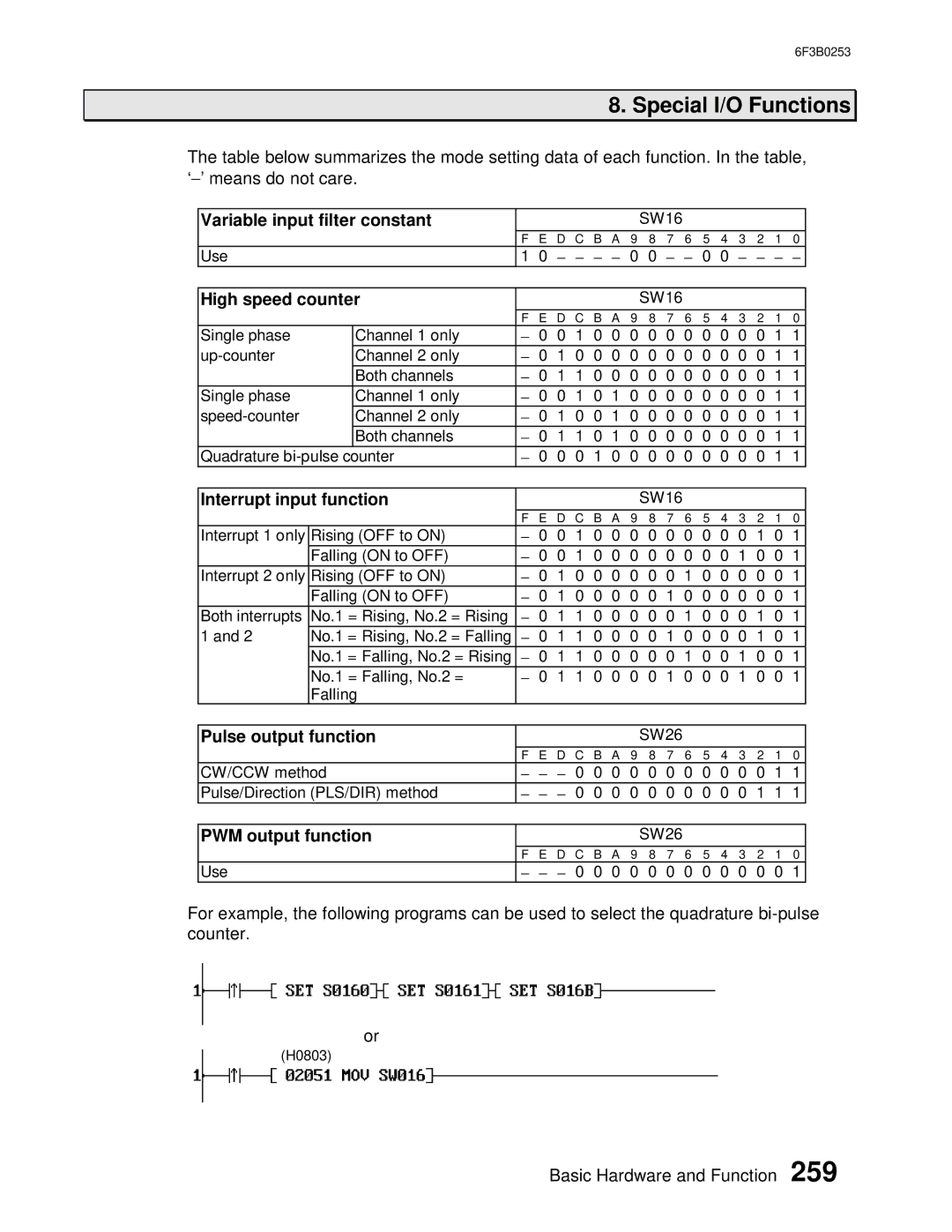
The table below summarizes the mode setting data of each function. In the table, ‘− ’ means do not care.
Variable input filter constant |
|
|
|
|
|
|
| SW16 |
|
|
|
|
|
| ||||
|
|
| F E D C B A 9 8 7 6 5 4 3 2 1 0 | |||||||||||||||
Use |
|
| 1 0 − | − | − − |
| 0 | 0 | − | − | 0 | 0 | − | − − | − |
| ||
|
|
|
|
|
|
|
|
|
|
|
|
|
|
|
|
| ||
High speed counter |
|
|
|
|
|
|
| SW16 |
|
|
|
|
|
| ||||
|
|
| F | E D C B A 9 8 7 6 5 4 3 2 1 0 | ||||||||||||||
Single phase |
| Channel 1 only | − | 0 | 0 | 1 | 0 | 0 | 0 | 0 | 0 | 0 | 0 | 0 | 0 | 0 | 1 | 1 |
| Channel 2 only | − | 0 | 1 | 0 | 0 | 0 | 0 | 0 | 0 | 0 | 0 | 0 | 0 | 0 | 1 | 1 | |
|
| Both channels | − | 0 | 1 | 1 | 0 | 0 | 0 | 0 | 0 | 0 | 0 | 0 | 0 | 0 | 1 | 1 |
Single phase |
| Channel 1 only | − | 0 | 0 | 1 | 0 | 1 | 0 | 0 | 0 | 0 | 0 | 0 | 0 | 0 | 1 | 1 |
| Channel 2 only | − | 0 | 1 | 0 | 0 | 1 | 0 | 0 | 0 | 0 | 0 | 0 | 0 | 0 | 1 | 1 | |
|
| Both channels | − | 0 | 1 | 1 | 0 | 1 | 0 | 0 | 0 | 0 | 0 | 0 | 0 | 0 | 1 | 1 |
Quadrature | − | 0 | 0 | 0 | 1 | 0 | 0 | 0 | 0 | 0 | 0 | 0 | 0 | 0 | 1 | 1 | ||
|
|
|
|
|
|
|
|
|
|
|
|
|
|
|
| |||
Interrupt input function |
|
|
|
|
|
|
| SW16 |
|
|
|
|
|
| ||||
|
|
| F | E D C B A 9 8 7 6 5 4 3 2 1 0 | ||||||||||||||
Interrupt 1 only | Rising (OFF to ON) | − | 0 | 0 | 1 | 0 | 0 | 0 | 0 | 0 | 0 | 0 | 0 | 0 | 1 | 0 | 1 | |
| Falling (ON to OFF) | − | 0 | 0 | 1 | 0 | 0 | 0 | 0 | 0 | 0 | 0 | 0 | 1 | 0 | 0 | 1 | |
Interrupt 2 only | Rising (OFF to ON) | − | 0 | 1 | 0 | 0 | 0 | 0 | 0 | 0 | 1 | 0 | 0 | 0 | 0 | 0 | 1 | |
| Falling (ON to OFF) | − | 0 | 1 | 0 | 0 | 0 | 0 | 0 | 1 | 0 | 0 | 0 | 0 | 0 | 0 | 1 | |
Both interrupts | No.1 = Rising, No.2 = Rising | − | 0 | 1 | 1 | 0 | 0 | 0 | 0 | 0 | 1 | 0 | 0 | 0 | 1 | 0 | 1 | |
1 and 2 | No.1 = Rising, No.2 = Falling | − | 0 | 1 | 1 | 0 | 0 | 0 | 0 | 1 | 0 | 0 | 0 | 0 | 1 | 0 | 1 | |
| No.1 = Falling, No.2 = Rising | − | 0 | 1 | 1 | 0 | 0 | 0 | 0 | 0 | 1 | 0 | 0 | 1 | 0 | 0 | 1 | |
| No.1 = Falling, No.2 = | − | 0 | 1 | 1 | 0 | 0 | 0 | 0 | 1 | 0 | 0 | 0 | 1 | 0 | 0 | 1 | |
| Falling |
|
|
|
|
|
|
|
|
|
|
|
|
|
|
|
| |
|
|
|
|
|
|
|
|
|
|
|
|
|
|
| ||||
Pulse output function |
|
|
|
|
|
|
| SW26 |
|
|
|
|
|
| ||||
|
|
| F E D C B A 9 8 7 6 5 4 3 2 1 0 | |||||||||||||||
CW/CCW method | − | − | − | 0 | 0 | 0 | 0 | 0 | 0 | 0 | 0 | 0 | 0 | 0 | 1 | 1 | ||
Pulse/Direction (PLS/DIR) method | − | − | − 0 | 0 | 0 | 0 | 0 | 0 | 0 | 0 | 0 | 0 | 1 | 1 | 1 | |||
|
|
|
|
|
|
|
|
|
|
|
|
|
|
| ||||
PWM output function |
|
|
|
|
|
|
| SW26 |
|
|
|
|
|
| ||||
|
|
| F E D C B A 9 8 7 6 5 4 3 2 1 0 | |||||||||||||||
Use |
|
| − | − | − | 0 | 0 | 0 | 0 | 0 | 0 | 0 | 0 | 0 | 0 | 0 | 0 | 1 |
For example, the following programs can be used to select the quadrature
or
(H0803)
Basic Hardware and Function 259