6F3B0253
1. System Configuration
Analog setting adjusters:
Two analog setting adjusters are provided. The V0 value is stored in SW30 and the V1 value is stored in SW31. The converted value range is 0 to 1000. Refer to section 8.5 for details of the analog setting function.
Programmer port connector:
Used to connect the programmer cable. The interface is
Expansion connector:
Used to connect the I/O module.
RS-485 port (Enhanced model only):
Used to connect a computer (SCADA system), operator interface unit, other
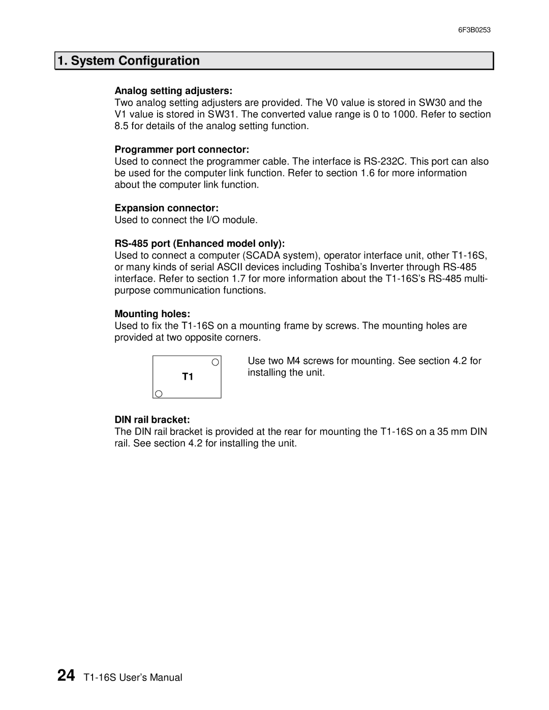
Mounting holes:
Used to fix the
T1
DIN rail bracket:
Use two M4 screws for mounting. See section 4.2 for installing the unit.
The DIN rail bracket is provided at the rear for mounting the
24
