6F3B0253
7. Instructions
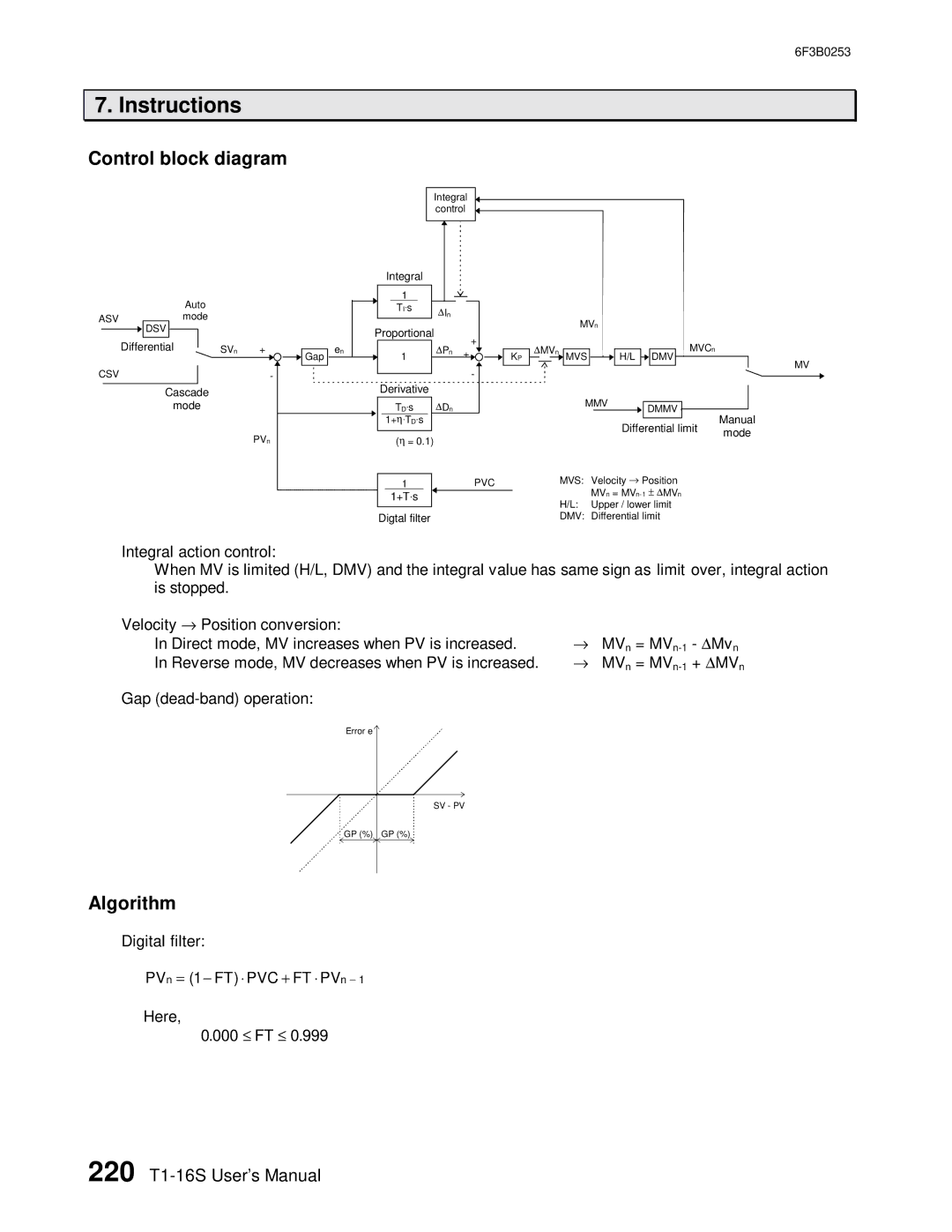
Control block diagram
|
|
|
|
| Auto |
| ||
ASV |
|
| mode |
| ||||
|
|
| DSV |
|
|
|
|
|
|
|
|
|
|
|
|
| |
|
|
|
|
|
|
|
|
|
| Differential |
|
| SVn | + | |||
|
| |||||||
CSV |
|
|
| - | ||||
|
|
| ||||||
|
|
|
|
|
| |||
|
|
| Cascade |
| ||||
|
|
|
| mode |
| |||
PVn
|
|
| Integral |
|
|
|
|
|
|
| ||
|
|
| control |
|
|
|
|
|
|
| ||
|
| Integral |
|
|
|
|
|
|
|
|
|
|
|
| 1 |
|
|
|
|
|
|
|
|
|
|
|
| TI⋅s | ∆ In |
|
|
|
|
|
|
|
| |
|
|
|
|
|
|
| MVn |
|
|
| ||
|
| Proportional |
|
|
|
|
|
|
|
| ||
|
|
|
| + |
|
|
|
|
|
| ||
| en |
| ∆ | Pn |
| ∆ | MVn |
|
| MVCn |
| |
Gap | 1 | + | KP | MVS | H/L |
| ||||||
|
| DMV | MV | |||||||||
|
|
|
|
|
| - |
|
|
|
|
| |
|
|
|
|
|
|
|
|
|
|
|
| |
|
| Derivative |
|
|
|
|
|
|
|
|
|
|
|
| TD⋅s | ∆ | Dn |
|
|
|
| MMV |
| DMMV |
|
|
| 1+η⋅ TD⋅s |
|
|
|
|
|
|
| Differential limit | Manual | |
|
| (η = 0.1) |
|
|
|
|
|
|
| mode | ||
|
|
|
|
|
|
|
|
|
|
| ||
|
|
|
|
|
|
|
|
|
|
|
| |
| 1 |
|
| PVC | MVS: | Velocity → Position | |
|
| 1+T⋅s |
|
|
|
| MVn = |
|
|
|
|
|
| H/L: | Upper / lower limit |
|
|
|
|
|
| ||
| Digtal filter |
|
| DMV: | Differential limit | ||
Integral action control:
When MV is limited (H/L, DMV) and the integral value has same sign as limit over, integral action is stopped.
Velocity → Position conversion: | → |
| - ∆ Mvn |
In Direct mode, MV increases when PV is increased. | MVn = | ||
In Reverse mode, MV decreases when PV is increased. | → | MVn = | + ∆ MVn |
Gap |
|
|
|
Error e |
|
|
|
SV - PV
![]()
![]() GP (%) GP (%)
GP (%) GP (%)
Algorithm
Digital filter:
PVn = (1− FT⋅) PVC+ FT⋅ PVn − 1
Here,
0.000 ≤ FT≤ 0.999
220