6F3B0253
4. Installation and Wiring
4.3 Wiring terminals
! CAUTION
1. Turn off power before wiring to minimize the risk of electrical shock.
2.Exposed conductive parts of wire can cause electrical shock. Use
3.Turn off power before removing or replacing units, modules, terminal blocks or wires. Failure to do so can cause electrical shock or damage to the
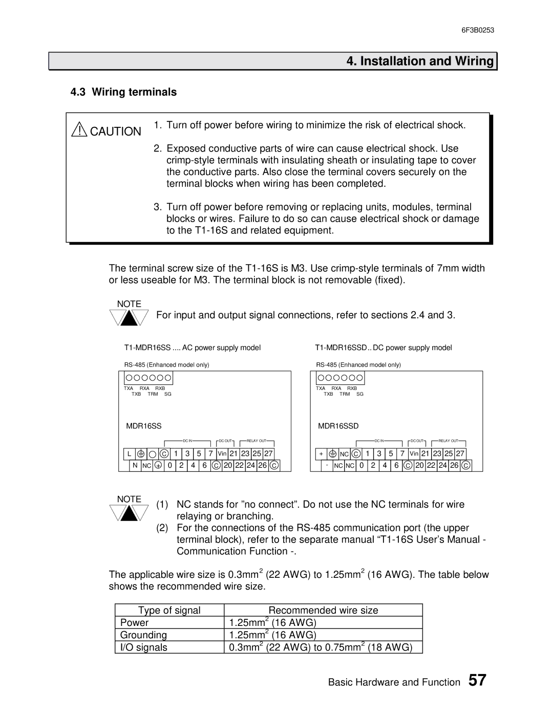
The terminal screw size of the
NOTE
For input and output signal connections, refer to sections 2.4 and 3.
TXA RXA RXB
TXB TRM SG
MDR16SS
|
|
|
|
|
|
|
|
|
|
|
|
|
| DC IN |
|
|
|
|
| DC OUT |
|
| RELAY OUT |
|
|
| ||||||||||
|
|
|
|
|
|
|
|
|
|
|
|
|
|
|
|
|
|
|
|
|
|
|
|
|
|
|
|
|
|
|
|
|
|
|
|
|
|
|
|
|
|
|
|
|
|
|
|
|
|
|
|
|
|
|
|
|
|
|
|
|
|
|
|
|
|
|
|
|
|
|
|
|
|
| L |
|
|
| − |
| C |
| 1 |
| 3 | 5 |
| 7 |
| Vin | 21 | 23 | 25 | 27 |
|
| ||||||||||||||
|
|
|
|
|
|
|
|
|
|
|
|
|
|
|
|
|
|
|
|
|
|
|
|
|
|
|
|
|
|
|
|
|
|
|
|
|
|
|
| N | NC | + |
| 0 |
| 2 |
| 4 |
| 6 |
| C | 20 | 22 | 24 | 26 | C |
| |||||||||||||||
|
|
|
|
|
|
|
|
|
|
|
|
|
|
|
|
|
|
|
|
|
|
|
|
|
|
|
|
|
|
|
|
|
|
|
|
|
TXA RXA RXB
TXB TRM SG
MDR16SSD
|
|
|
|
|
|
|
|
|
|
|
| DC IN |
|
|
|
|
|
| DC OUT |
|
| RELAY OUT |
|
|
| |||||||||
|
|
|
|
|
|
|
|
|
|
|
|
|
|
|
|
|
|
|
|
|
|
|
|
|
|
|
|
|
|
|
|
|
|
|
|
|
|
|
|
|
|
|
|
|
|
|
|
|
|
|
|
|
|
|
|
|
|
|
|
|
|
|
|
|
|
|
|
|
|
| + |
|
| NC | C |
| 1 |
| 3 |
| 5 |
| 7 | Vin | 21 | 23 | 25 | 27 |
|
| ||||||||||||||
|
|
|
|
|
|
|
|
|
|
|
|
|
|
|
|
|
|
|
|
|
|
|
|
|
|
|
|
|
|
|
|
|
|
|
|
| - | NC | NC | 0 |
| 2 |
| 4 |
| 6 |
| C | 20 | 22 | 24 | 26 | C |
| |||||||||||||||
|
|
|
|
|
|
|
|
|
|
|
|
|
|
|
|
|
|
|
|
|
|
|
|
|
|
|
|
|
|
|
|
|
|
|
NOTE
(1) NC stands for ”no connect”. Do not use the NC terminals for wire relaying or branching.
(2) For the connections of the
The applicable wire size is 0.3mm2 (22 AWG) to 1.25mm2 (16 AWG). The table below shows the recommended wire size.
Type of signal | Recommended wire size | |
Power | 1.25mm2 | (16 AWG) |
Grounding | 1.25mm2 | (16 AWG) |
I/O signals | 0.3mm2 (22 AWG) to 0.75mm2 (18 AWG) | |
Basic Hardware and Function 57