6F3B0253
7. Instructions
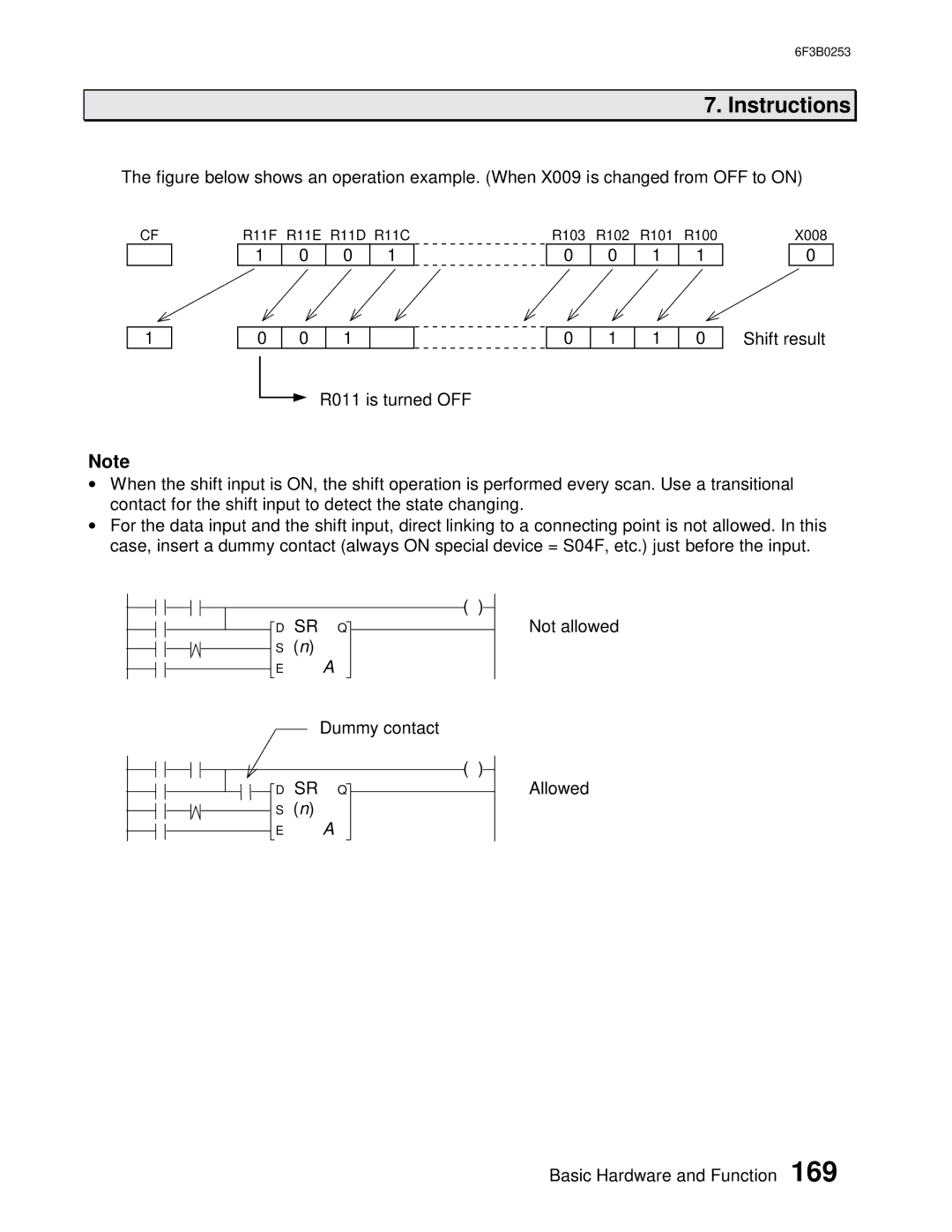
The figure below shows an operation example. (When X009 is changed from OFF to ON)
CF
1
R11F R11E R11D R11C
1 | 0 | 0 | 1 |
0 | 0 | 1 |
|
R011 is turned OFF
R103 R102 R101 R100
0 | 0 | 1 | 1 |
0 | 1 | 1 | 0 |
X008
0
Shift result
Note
•When the shift input is ON, the shift operation is performed every scan. Use a transitional contact for the shift input to detect the state changing.
•For the data input and the shift input, direct linking to a connecting point is not allowed. In this case, insert a dummy contact (always ON special device = S04F, etc.) just before the input.
|
| ( | ) | ||
D SR | Q |
|
| Not allowed | |
| |||||
S | (n) |
|
|
|
|
E |
| A |
|
|
|
Dummy contact
( )
![]()
![]()
![]()
![]()
![]() D SR Q
D SR Q
S (n)
E A
Allowed
Basic Hardware and Function 169